
 영어
영어 中文简体
中文简体 Русский
 Español
 Português
 Türkçe
 العربية
 Deutsch
 Polski
 Italiano
 Français
 한국어
한국어 ไทย
ไทย Tiếng Việt
 日本語
日本語





























흡수 클램프
사용자 설명서
적용 할 수있는 LISUN 모델: AB-CLP
1. 장비에 대한 기본 이해
1.1 제품 개요
1.1.1 주요 매개변수
| 파라미터 | 표시 | 노트 |
| 주파수 범위 | 30MHz ~ 1000MHz | 정격 동작 주파수 대역 |
| 출력 임피던스 | 50 Ω | Matching Coaxial System |
| Allowed cable diameter for testing | ≤20 mm | 규격을 초과하면 장비가 손상될 수 있습니다. |
| 신호 커넥터 | 유형 N | 출력 포트 |
| 흡수 클램프 계수 CF | -4dB ~ 4dB | 즉, 보정 계수 K는 주파수에 따라 변합니다. |
| 분리 계수(DF) | ≥21 dB | Ensure isolation between the test side and the power supply side |
| 분리 계수 DR | ≥30 dB | 동축 케이블 차폐의 분리 기능 |
| 크기 | 640mm (L) × 109mm (W) × 100mm (H) | |
| 중량(평량) | 5의 kg | |
1.1.2 응용 시나리오
The AB-CLP Absorbing Clamp (ACA) is a specialized device used for disturbance power testing in the field of electromagnetic compatibility (EMC) and serves as an alternative measurement device for radiated emission testing. By coupling and extracting common-mode disturbance power from the cable under test, it indirectly evaluates the device’s radiated emission levels. Since it does not require a large anechoic chamber, it can significantly reduce testing costs and shorten testing cycles, and is widely used in product R& D debugging and pre-compliance testing scenarios.
1.2 Scope of Application and Basis for Standards
1.2.1 장비 및 방법 표준
The performance of this system’s equipment and the test methods fully comply with the following international and national standards:
Equipment Specifications: CISPR 16-1-3, GB/T 6113.103 (Specifications for Equipment for the Measurement of Radio Disturbance and Immunity—Part 3: Equipment for the Measurement of Disturbance Power)
Test Method Standards: CISPR 16-2-2, GB/T 6113.202 (Methods for Measuring Radio Disturbance and Immunity—Part 2: Measurement of Disturbance Power)
1.2.2 Applicable Products and Test Frequencies
흡수 클램프 방식은 주로 장비가 전원 및 신호선을 통해 방출하는 전자기 간섭을 평가하는 데 사용됩니다. 필수 테스트 주파수 대역은 제품 표준에 따라 다릅니다.
The 30 MHz to 300 MHz frequency range (which provides full coverage when used with the EMI-9KB)
이는 대다수 제품에 대해 의무적으로 실시해야 하는 적합성 테스트 범위입니다. 해당 제품 표준은 다음과 같습니다.
CISPR 14-1 / GB 4343.1: 전자파 적합성 - 가전제품, 전동공구 및 유사 장비의 방출 요구사항; CISPR 15 / GB 17743: 전기 조명 및 유사 장비의 무선 간섭 특성.
300 MHz to 1000 MHz (requires use with the EMI-9KC 수화기)
The AB-CLP Absorbing Clamp has a rated frequency range of 30 MHz to 1000 MHz, while the EMI-9KC 수신기의 최대 주파수 제한은 1000MHz입니다.
When testing products such as audio-video receivers and multimedia devices (in accordance with standards such as CISPR 13 and CISPR 32), the standards require evaluation of disturbance power across the entire 30 MHz to 1000 MHz frequency band.
1.3 장비 구성 검증
1.3.1 포장 풀기
When unpacking the device, handle it gently to avoid scratching the exterior with sharp tools. After unpacking, first inspect the exterior of the device to ensure there is no visible deformation or dents, and that the buttons are not damaged or loose. If you notice any abnormalities with the device or its accessories, please contact us immediately.
1.3.2 본체 및 부속품
그림 1-1를 참조하세요.
| 번호 | 주의 사항 |
| ① | AB-CLP 흡수 클램프 |
| ② | 동축 케이블 |
| ③ | 6dB 동축 감쇠기 |
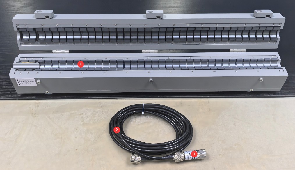
그림 1-1
1.3.3 전자 문서 다운로드
Links to the electronic user manual, warranty card, calibration certificate, and other documents have been sent via email. If you missed the email, please contact us to receive the links again.
2. 안전상의 주의
2.1 전기 안전
The device under test and the receiver must each be connected to the power grid via an Isolation Transformer that meets the appropriate specifications. Direct connection to the mains power supply is strictly prohibited to prevent power surges and the risk of electric shock.
별도의 신뢰할 수 있는 접지 시스템을 설치해야 하며, 접지 저항이 낮을수록 테스트 결과의 정확도가 높아집니다. 고출력 전기 장비와 접지 전극을 공유하는 것은 엄격히 금지되며, 모든 장비의 접지 단자는 접지 전극에 단단히 연결되어야 합니다.
Do not use the equipment if the power connections are loose or the cable sheath is damaged; during thunderstorms, disconnect all equipment from the power source and ground connections to prevent damage from lightning strikes.
수신기의 RF 입력 포트는 민감한 RF 인터페이스이므로 고전압 또는 고레벨 신호를 직접 연결하지 마십시오. 내부 회로가 손상될 수 있습니다.
2.2 작동 안전
Strictly follow the sequence: “Turn on the peripherals first, then the computer; turn off the computer first, then the peripherals.”
Before powering on or off the device under test, you must first disconnect the coaxial cable from the front end of the receiver to prevent switching transients from damaging the receiver’s internal circuitry; under no circumstances should you plug in or unplug the coaxial cable during testing.
When opening and closing the Absorbing Clamps, operate them smoothly to avoid pinching your hands; do not insert cables or hard metal objects with a diameter greater than 20 mm into the jaws to prevent the internal ferrite cores from cracking.
시험 중에는 흡수 클램프를 부드럽게 밀고 당겨서 이동시켜 슬라이드 레일에 강한 충격을 주지 않도록 하십시오. 이렇게 하면 시험 정확도에 영향을 줄 수 있는 내부 부품의 변위를 방지할 수 있습니다.
제조업체의 허가 없이는 흡수 클램프 또는 수신기 장치의 케이스를 분해하지 마십시오. 그렇지 않으면 보증이 무효화됩니다.
2.3 환경 안전
The equipment operating environment temperature is 5–35°C, with a relative humidity of ≤80% and no condensation; flammable, explosive, or corrosive materials must not be stored in the test area.
It is recommended that formal testing be conducted in an electromagnetically shielded room; for preliminary testing, select a separate room located far from sources of strong electromagnetic interference—such as variable-frequency drives, arc welders, high-power chargers, and wireless transmitting equipment—to minimize the impact of environmental background noise.
The test area must be at least 0.8 m away from walls and other large conductive objects to prevent electromagnetic wave reflections from affecting the test results.
3. 보조 장비 및 시스템 배선 소개
3.1 EMI-9KB 리시버
3.1.1 전면 패널
그림 3-1를 참조하세요.
| 번호 | 주의 사항 |
| ① | 전원 스위치 |
| ② | RF 입력 포트는 다음과 연결됩니다. AB-CLP using a coaxial attenuator and coaxial cable |
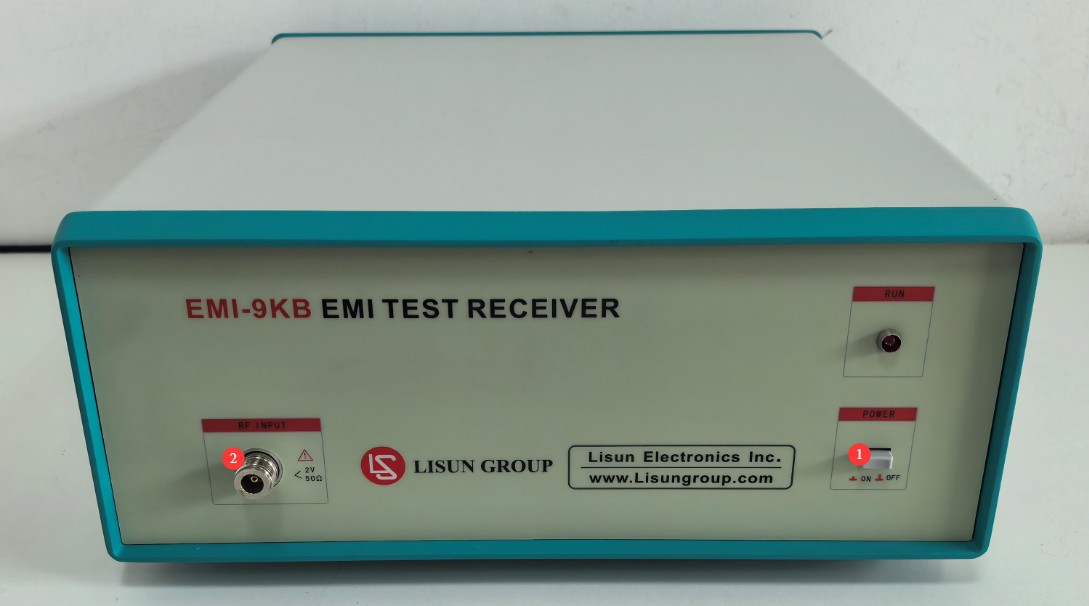
그림 3-1
3.1.2 후면 패널
그림 3-2를 참조하세요.
| 번호 | 주의 사항 |
| ① | 절연 변압기에 연결된 전원 코드 잭 |
| ② | 퓨즈 |
| ③ | RS-232 communication port: Connect to a computer using an RS-232 cable. If the computer does not have an RS-232 port, you can use the standard RS-232-to-USB adapter cable to connect to the computer. Note: Do not use non-standard cables or adapters, as this may cause communication errors. |
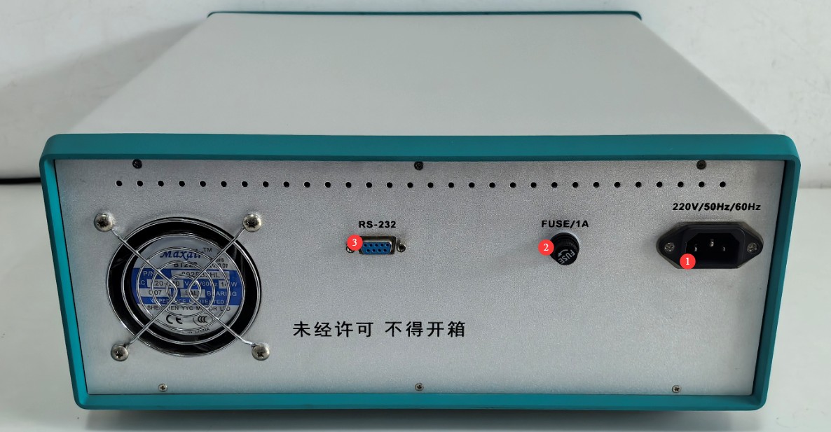
그림 3-2
3.2 Test System Wiring Procedure
안정적인 연결을 위해 다음 순서대로 시스템 배선을 완료해 주십시오.
| 배선 방법 | 주의 사항 |
| ① Power Supply Circuit Wiring | Connect Isolation Transformer 1 to the mains power supply; use its output to connect the power supply circuit for the device under test. Connect Isolation Transformer 2 to the mains power supply; connect its output to the EMI-9KB 수신기와 컴퓨터. |
| ② Wiring the Absorber Clamp to the Receiver | 6dB 동축 감쇠기를 N형 출력 포트에 나사로 고정하십시오. AB-CLP 흡수 클램프; 동축 케이블의 한쪽 끝을 6dB 감쇠기에 연결하고 다른 쪽 끝을 RF 입력 포트에 연결합니다. EMI-9KB 수신기. |
| ③ Communication Wiring | 사용 RS232 한쪽 끝을 연결하는 케이블 RS232 수신기의 후면 패널에 있는 포트와 다른 한쪽 끝을 컴퓨터에 직접 또는 간접적으로 연결합니다. RS232USB 어댑터. |
| ④ Grounding Connection | Reliably connect the receiver’s ground terminal and the metal reference ground plate used for testing to a separate ground electrode using a copper ground wire. |
4. EMI-9KB 소프트웨어 설치 및 개요
4.1 소프트웨어 및 드라이버 설치
4.1.1 시스템 운영 요구사항
운영 체제: Windows 7 / Windows 8 / Windows 10 / Windows 11; Windows 10을 권장합니다.
Hardware Requirements: Pentium or higher processor, ≥2 GB of RAM, ≥1 GB of free hard drive space, and at least one available USB port;
화면 해상도: 1024×768 이상을 권장합니다.
4.1.2 설치
그림 4-1를 참조하세요.
| 번호 | 주의 사항 |
| ① | EMI-9KB 수신기 PC 소프트웨어 - 두 번 클릭하여 설치하세요 |
| ② | RS-232-USB 어댑터 드라이버: RS-232-USB 어댑터를 사용하는 경우 이 드라이버를 설치해야 합니다. |

그림 4-1
4.1.3 통신 포트 설정
소프트웨어를 처음 실행할 때 그림 4-2와 같이 통신 오류 메시지가 나타날 수 있습니다.
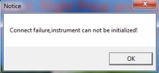
그림 4-2
확인을 클릭하여 소프트웨어의 초기 인터페이스를 열고 그림 4-3과 같이 테스트 > 포트 설정을 클릭합니다.
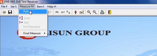
그림 4-3
그림 4-4에 표시된 것처럼 올바른 통신 포트 번호를 수동으로 선택하기만 하면 됩니다.
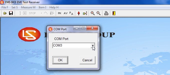
그림 4-4
As shown in Figures 4 and 5, you can go to “My Computer” > “Properties” > “Device Manager” to verify the communication port used by the device.
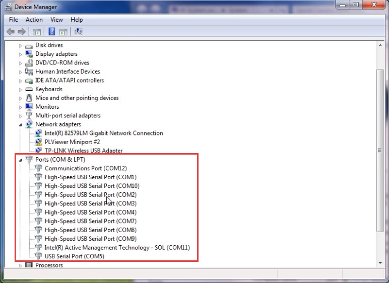
그림 4~5
The next time you open the software, it will open directly to the initial interface. Note: If the communication port changes, you will need to reselect the correct communication port.
4.2 소프트웨어 인터페이스 기능 소개
4.2.1 파일 메뉴
4.2.1.1 드롭다운 목록
그림 4~6을 참조하십시오.
| 번호 | 주의 사항 |
| ① | EMC 파일을 엽니다. |
| ② | 테스트 결과를 emc 파일로 저장하세요. 참고: emc 파일은 특정 프로그램으로만 열 수 있습니다. LISUN EMI-9KB 소프트웨어. |
| ③ | 테스트 보고서 설정 |
| ④ | Print a report that includes data from the final test points |
| ⑤ | 관심 지점에 대한 데이터가 포함된 보고서를 출력하세요. |
| ⑥ | 소프트웨어를 종료합니다 |
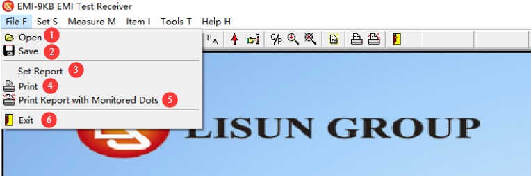
그림 4~6
4.2.1.2 보고서 옵션 정보
시험 보고서를 저장하거나 인쇄할 때 그림 4-7과 같이 다음 화면이 먼저 나타납니다.
| 번호 | 주의 사항 |
| ① | 최종 검사 지점/집중 지점 데이터를 저장/인쇄하시겠습니까? |
| ② | 시험 관련 정보를 입력하세요 |
| ③ | 실험실 정보를 입력하세요 |
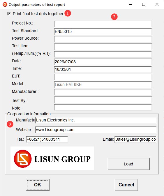
그림 4-7
4.2.2 설정 메뉴
4.2.2.1 드롭다운 목록
그림 4~8을 참조하십시오.
| 번호 | 주의 사항 |
| ① | 시험 기준: 기준 선택, 추가, 편집 또는 삭제 |
| ② | 테스트 매개변수: 변경할 필요 없이 기본 설정을 그대로 사용하십시오. |
| ③ | System Calibration: Used by professional engineers when commissioning the equipment; this function is not required during normal operation. |
| ④ | 감쇠기: 실제 상황에 따라 선택하십시오. |
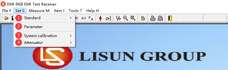
그림 4-8
4.2.2.2 테스트 표준 옵션
그림 4~9을 참조하십시오.
| 번호 | 주의 사항 |
| ① | 선택 기준: 이전에 추가된 기준만 선택할 수 있으며, 기준의 매개변수는 수정할 수 없습니다. |
| ② | 표준을 추가, 수정 또는 삭제할 수 있습니다. 주의: 신중하게 진행하십시오. 모든 표준 및 한계 곡선은 제공된 표준에 따라 추가됩니다. 당사 소프트웨어에 포함되지 않은 다른 표준 데이터가 있는 경우 관련 표준을 보내주시면 추가해 드리겠습니다. |
| ③ | 흡수 클램프, 전압 프로브, CDN 네트워크 보정. 참고: 다음 사용자만 사용 가능 LISUN 소프트웨어 디버깅을 할 때 전문 엔지니어들이 하는 일입니다. |
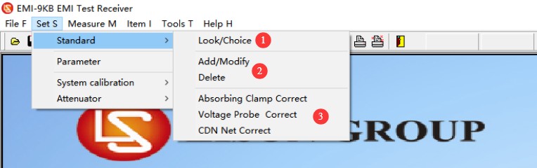
그림 4-9
4.2.2.3 감쇠기 옵션
그림 4-10를 참조하세요.
| 번호 | 주의 사항 |
| ① | 감쇠기를 사용하지 마십시오. |
| ② | 감쇠기를 사용할 때는 소프트웨어에서 올바른 감쇠 매개변수를 선택하여 입력하십시오. |
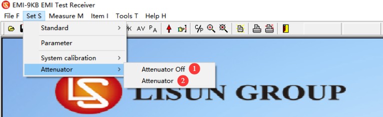
그림 4-10
참고: 연결할 때 EMI-9KB 부터 AB-CLP6dB 감쇠기도 연결해야 합니다. 사용 전에 올바른 감쇠기 매개변수를 설정하십시오.
4.2.3 테스트 메뉴
그림 4-11를 참조하세요.
| 번호 | 주의 사항 |
| ① | 통신 포트 설정에 대해서는 4.1.3절을 참조하십시오. |
| ② | 스캔: 선택한 기준 및 매개변수 설정에 따라 스캔 테스트를 수행합니다. |
| ③ | 부분 테스트: 특정 주파수 지점의 데이터만 보려면 여기를 클릭하여 주파수를 수동으로 입력하고 테스트를 실행하세요. |
| ④ | 최종 테스트: 스캔 테스트가 완료된 후 특정 지점의 데이터를 다시 테스트하려면 최종 테스트를 수행할 수 있습니다. |
| ⑤ | 자동 최종 테스트: 소프트웨어는 테스트 결과를 바탕으로 최종 테스트를 위한 대표적인 주파수 지점을 자동으로 선택합니다. |
| ⑥ | Manual Final Test: Users manually add the frequency points to be tested based on their needs. |
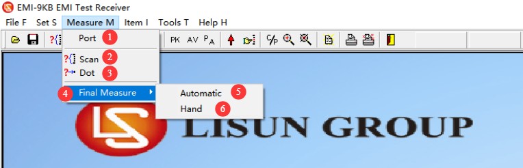
그림 4-11
4.2.4 디스플레이 메뉴
그림 4-12를 참조하세요.
| 번호 | 주의 사항 |
| ① | 이 그래프는 기본 PK 및 AV 라인을 모두 보여줍니다. |
| ② | 모니터링 지점을 추가하세요. 이 기능은 버전 4.2.3의 최종 테스트와 동일하게 작동하며, 모니터링 빈도를 수동으로 설정할 수 있습니다. |
| ③ | 한계 곡선을 벗어나는 데이터를 표시합니다. |
| ④ | 최종 테스트 지점의 데이터를 표시합니다. |
| ⑤ | 연속으로 두 번의 스캔 테스트를 수행한 후, 클릭하여 두 테스트 결과를 비교할 수 있습니다. |
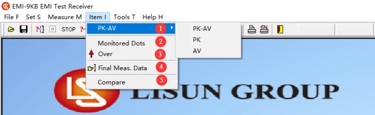
그림 4-12
4.2.5 탐색 모음 바로가기 키 소개
그림 4-13를 참조하세요.
| 번호 | 주의 사항 |
| ① | EMC 파일을 엽니다. |
| ② | emc 파일로 저장 |
| ③ | 스캔 테스트 |
| ④ | 테스트 일시 중지 |
| ⑤ | 테스트 중지 |
| ⑥ | 지점 측정 |
| ⑦ | 자동화된 최종 테스트 |
| ⑧ | 수동 최종 테스트 |
| ⑨ | 표시 곡선: PK, AV, PK+AV |
| ⑩ | 한계 곡선을 벗어나는 데이터를 표시합니다. |
| ⑪ | 최종 체크포인트에 대한 표시 데이터 |
| ⑫ | 겹치는 데이터 포인트를 표시하거나 숨깁니다(겹치는 데이터 포인트를 숨기면 곡선이 더 명확해집니다). |
| ⑬ | 확대/축소: 곡선을 확대하여 더 쉽게 볼 수 있습니다. 클릭 후, 곡선 표시 영역에서 마우스 가운데 버튼 휠을 돌려 확대 또는 축소하세요. |
| ⑭ | 테스트 보고서 설정 |
| ⑮ | 최종 테스트 지점 데이터가 포함된 보고서를 출력하세요. |
| ⑯ | 관심 지점에 대한 데이터가 포함된 보고서를 출력하세요. |
| ⑰ | 소프트웨어를 종료합니다 |
| ⑱ | 기기 내부 모듈의 매개변수를 표시합니다. 디버깅 시 전문 엔지니어만 사용할 수 있습니다. |
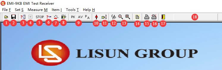
그림 4-13
5. 사전 테스트 준비 및 시스템 설정
5.1 테스트 환경 요구사항
Shielded Room Solution (Compliance Testing): Formal conformity assessment testing must be conducted in a standard-compliant electromagnetic shielded room that completely isolates the test equipment from external interference, ensuring the authority of the test results.
Standard Room Specifications (Preliminary Testing): For R& D preliminary testing, a dedicated room with an area of at least 15 square meters and free of other devices that generate strong electromagnetic interference should be used. Priority should be given to rooms on the first floor to facilitate grounding and reduce grounding resistance.
Sufficient space must be reserved in the test area to accommodate the length of the slide rails and the required spacing between equipment.
5.2 Requirements for Standard Test Setups
시험 환경은 CISPR 16-2-2 / GB/T 6113.202 표준의 요구 사항을 엄격히 준수하며, 시험 대상 장비 유형에 따라 데스크탑형과 플로어 스탠딩형의 두 가지 구성으로 나뉩니다.
5.2.1 시험 대상 장비(EUT)의 벤치탑 배치
그림 5-1를 참조하십시오(CISPR 16-2-2, 그림 8에서 발췌).
절연 시험대를 지면 기준면보다 0.8m 높은 곳에 설치하고, 시험 대상 장비를 시험대 위에 단단히 고정하되, 장비 뒷면이 금속 벽이나 지면 기준면에서 0.4m 떨어지도록 합니다.
절연 슬라이드 레일(높이 0.8m)을 수평으로 설치하십시오. 레일은 최소 6m 길이여야 하며, 테스트 대상 장비와 동일한 수평면에 위치해야 합니다.
The lead under test (LUT) must be straightened and placed horizontally, with one end connected to the device under test and the other end extending along the slide rail and hanging naturally to the ground, where it is connected to a power source; The total length of the lead under test shall be no less than 7.5 m (including a 6 m section on the slide rail, a 1 m hanging section, and a 0.5 m allowance). If the length of the equipment’s original power cord is insufficient, it must be extended using a replacement cord of the same type and construction.
Open the Absorbing Clamp, insert the wire to be tested into the center hole of the Clamp, close the Clamp, and secure the latch; place the Absorbing Clamp on the slide rail so that it can slide freely along the rail.
슬라이드 레일 기준점(SRP)과 클램프 기준점(CRP) 사이의 초기 거리는 10 ± 1 cm로 설정됩니다. 이 거리는 시험 결과에 상당한 영향을 미치므로 엄격하게 제어해야 합니다.
감쇠기, 동축 케이블 및 EMI-9KB 3장에 명시된 대로 수신기를 흡수 클램프의 출력에 연결합니다. 테스트 영역과의 간섭을 피하기 위해 수신기를 슬라이드 레일 끝의 바깥쪽에 배치합니다.
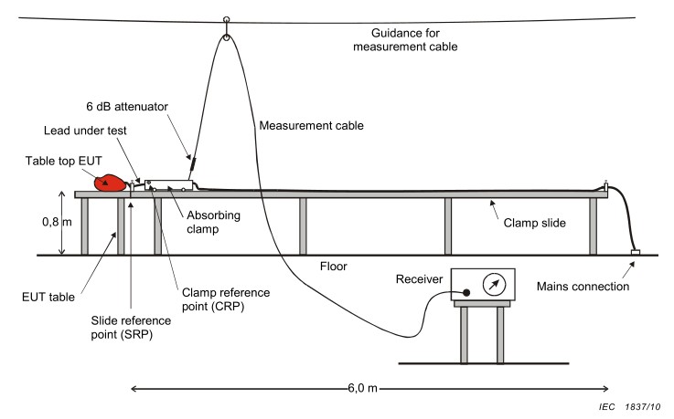
그림 5-1
5.2.2 Floor-Standing Equipment Under Test (EUT) Setup
그림 5-2를 참조하십시오(CISPR 16-2-2, 그림 9에서 발췌).
Place a metal grounding reference plate measuring at least 2 m × 2 m on the floor. Place an insulating mat 0.1 m high on top of the metal plate, and carefully place the device under test on the insulating mat.
The insulated rail remains at a height of 0.8 m and is positioned horizontally next to the equipment under test; the rest of the wiring layout, absorption clamp installation, and spacing requirements are the same as those for the benchtop unit.
All surfaces of the device under test must be at least 50 cm from the edge of any metal plate and at least 80 cm from any conductive objects in the vicinity.
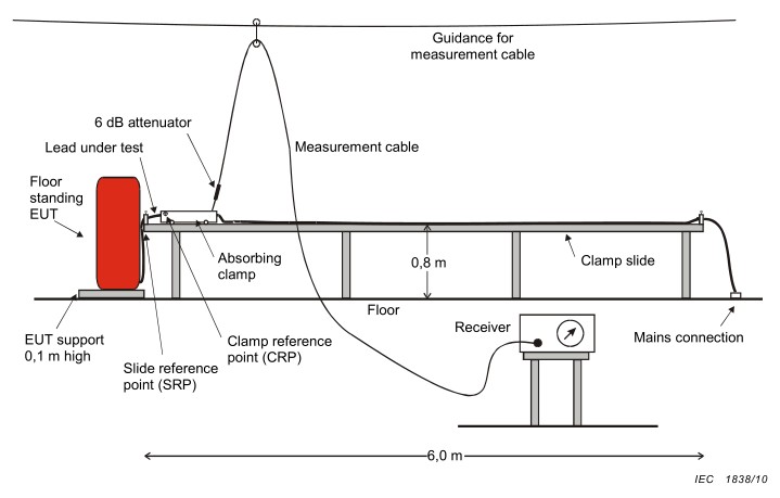
그림 5-2
6. 간섭 전력 테스트 절차
6.1 Powering On and Warm-Up
먼저 절연 변압기를 켜고, 그 다음 전원을 켜십시오. EMI-9KB 수신기를 연결하고 마지막으로 컴퓨터를 켜고 테스트 소프트웨어를 실행합니다.
수신기를 켠 후 10분간 예열하십시오. 내부 회로가 안정화될 때까지 기다린 후 테스트를 시작하십시오.
테스트 대상 장치의 전원을 켜서 정상 작동 모드로 전환하고, 표준 요구 사항에 따라 안정적인 작동 상태에 도달할 때까지 예열하십시오(일반적으로 15~30분).
6.2 Confirmation of Test Parameters
6.2.1 표준 선정
섹션 4.2.2.2를 참조하십시오. 표준 선택 메뉴로 이동하여 "Power"라고 표시된 표준을 선택하십시오. 이것이 흡수형 클램프용 표준입니다. 그림 6-1을 참조하십시오.
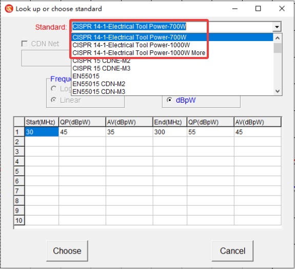
그림 6-1
6.2.2 감쇠기 설정
섹션 4.2.2.3을 참조하여 그림 6-2에 표시된 대로 6dB 감쇠기를 선택하십시오.
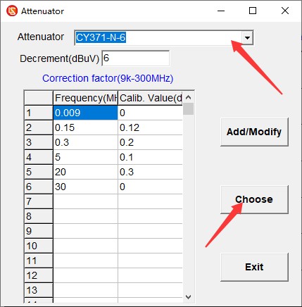
그림 6-2
6.4 스캔 테스트
Click “Scan Test,” wait for the scan to complete, and if any issues arise, click “Stop Test,” make the necessary adjustments, and then restart the test. The scan is complete; see Figure 6-3.
붉은 선: 준정점(QP) 한계선;
파란색 선: 평균(AV) 한계선;
녹색 곡선: 피크(PK) 테스트 곡선;
파란색 곡선: 평균(AV) 검사 곡선.
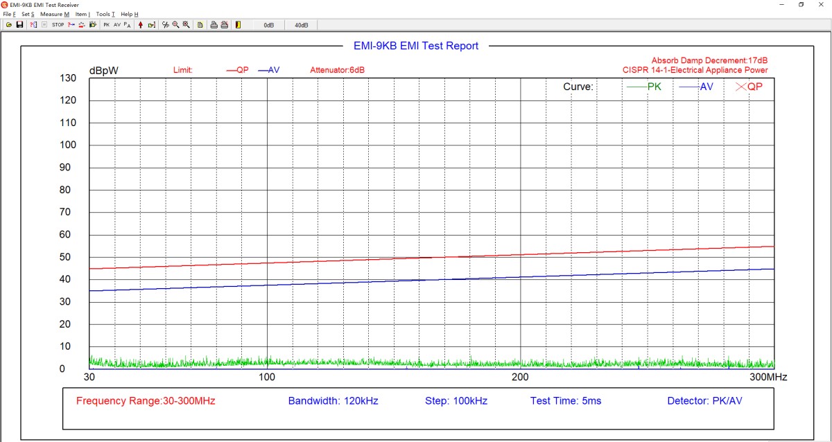
그림 6-3
6.5 최종 시험
If the average values (AV) of the test results are all below the limit curve, and the peak values (PK) are all below the quasi-peak (QP) limit curve, then the EUT meets the standard requirements, because the actual quasi-peak (QP) value measured during testing will not exceed the peak (PK) value. If the tested peak value (PK) exceeds the quasi-peak (QP) limit curve, the EUT does not necessarily fail to meet the standard requirements; a final test must be conducted.
6.5.1 자동 최종 테스트
테스트할 주파수 포인트 수를 입력하면 소프트웨어가 그림 6-4과 같이 테스트 곡선을 기반으로 주파수 포인트를 자동으로 선택하여 최종 테스트를 수행합니다.
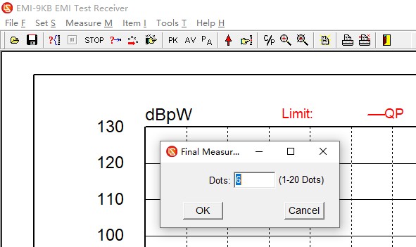
그림 6-4
6.5.2 수동 최종 테스트
In the software test curve area, right-click on the point where you want to perform the final test, as shown in Figure 6-5.
| 번호 | 주의 사항 |
| ① | 엔드포인트 추가 |
| ② | 끝점 삭제 |
| ③ | 필요한 최종 테스트 항목을 모두 입력한 후 "최종 테스트 시작"을 클릭하십시오. |
| ④ | 최종 시험에 더 이상 참여하고 싶지 않으시면 “최종 시험 취소”를 클릭하세요. |
| ⑤ | 파란색 마름모는 추가된 최종 테스트 지점의 위치를 나타냅니다. |
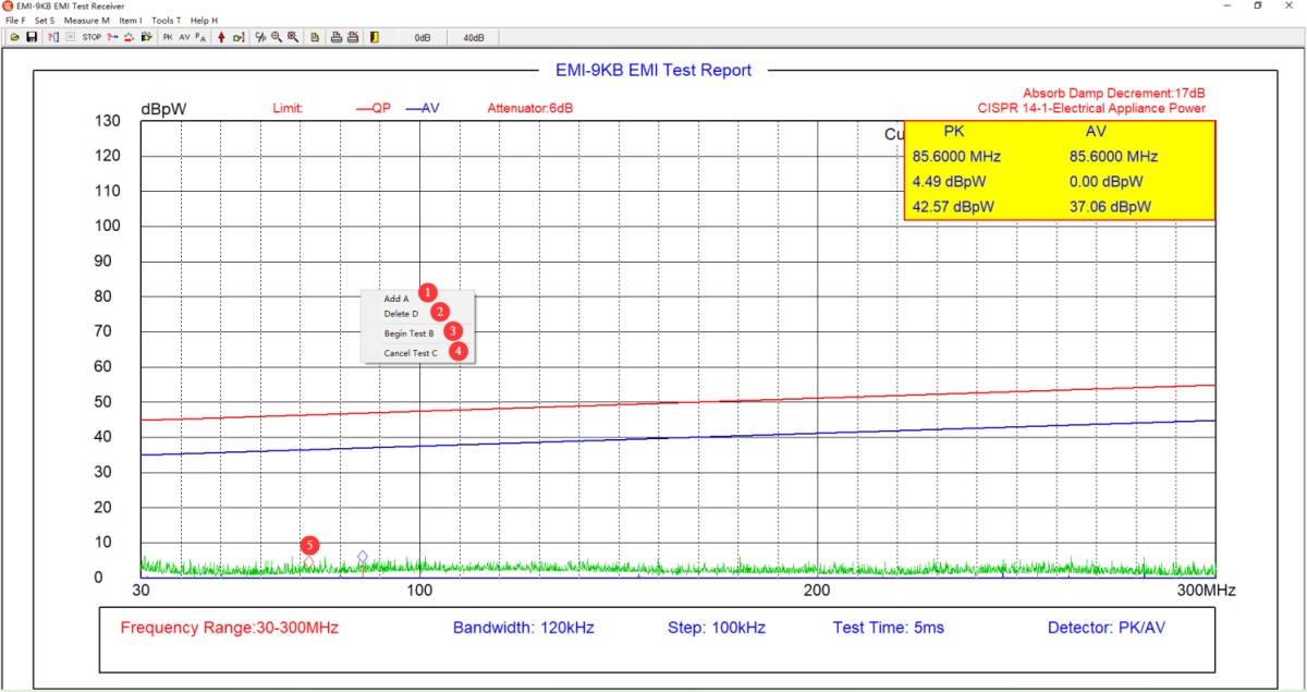
그림 6-5
6.5.3 관심 지점 추가
그림 6-6를 참조하세요.
| 번호 | 주의 사항 |
| ① | 현재 화면에서 모든 주파수 지점과 데이터를 지우려면 클릭하십시오. |
| ② | 주파수 지점 상태를 편집하려면 탭하세요. 주파수 지점 편집 모드를 종료하려면 다시 탭하세요. |
| ③ | 주파수 편집 지점입니다. 각 주파수 지점을 수동으로 입력할 수 있습니다. |
| ④ | 이전에 편집한 주파수 포인트 파일을 직접 불러올 수 있습니다. |
| ⑤ | 현재 편집 중인 빈도 데이터 파일을 저장하여 최종 테스트 중에 바로 접근할 수 있습니다. |
| ⑥ | "데이터 생성"을 클릭하면 현재 테스트 보고서에서 해당 주파수 지점의 테스트 데이터를 직접 읽어올 수 있습니다. |
| ⑦ | 현재 테스트 보고서에서 해당 주파수 지점의 테스트 데이터를 읽으십시오. |
| ⑧ | 검색된 데이터를 삭제하려면 "데이터 삭제"를 클릭하십시오. |
| ⑨ | 현재 초점 위치 데이터를 테스트 보고서에 저장하려면 확인을 클릭하십시오. |
| ⑩ | 현재 화면의 포커스 위치 데이터를 저장하지 않고 즉시 종료하려면 [종료]를 클릭하십시오. |
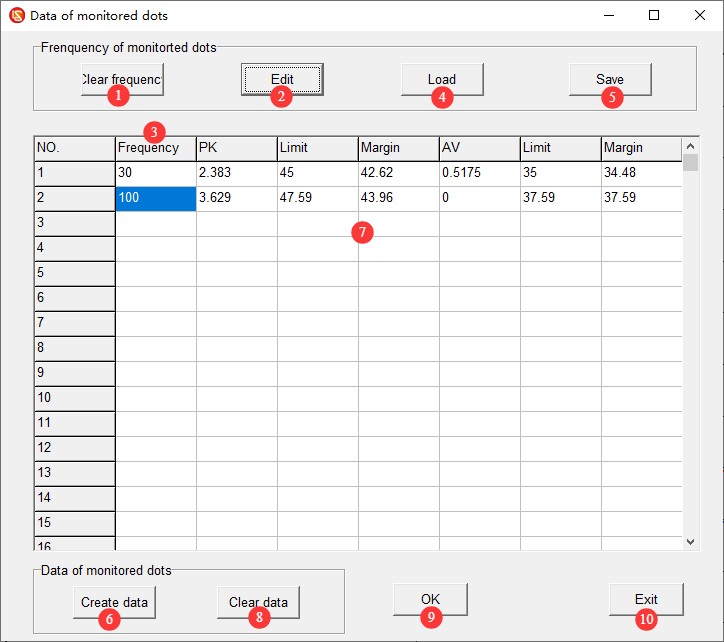
그림 6-6
6.5.4 최종 시험 데이터 해석
그림 6~7을 참조하십시오. 빨간색 X는 최종 테스트에서 얻은 준피크(QP) 값을 나타냅니다. 최종 테스트에서 얻은 모든 준피크(QP) 값이 준피크(QP) 한계 곡선보다 낮으면 EUT는 표준 요구 사항을 충족합니다. 그렇지 않으면 표준 요구 사항을 충족하지 못합니다.
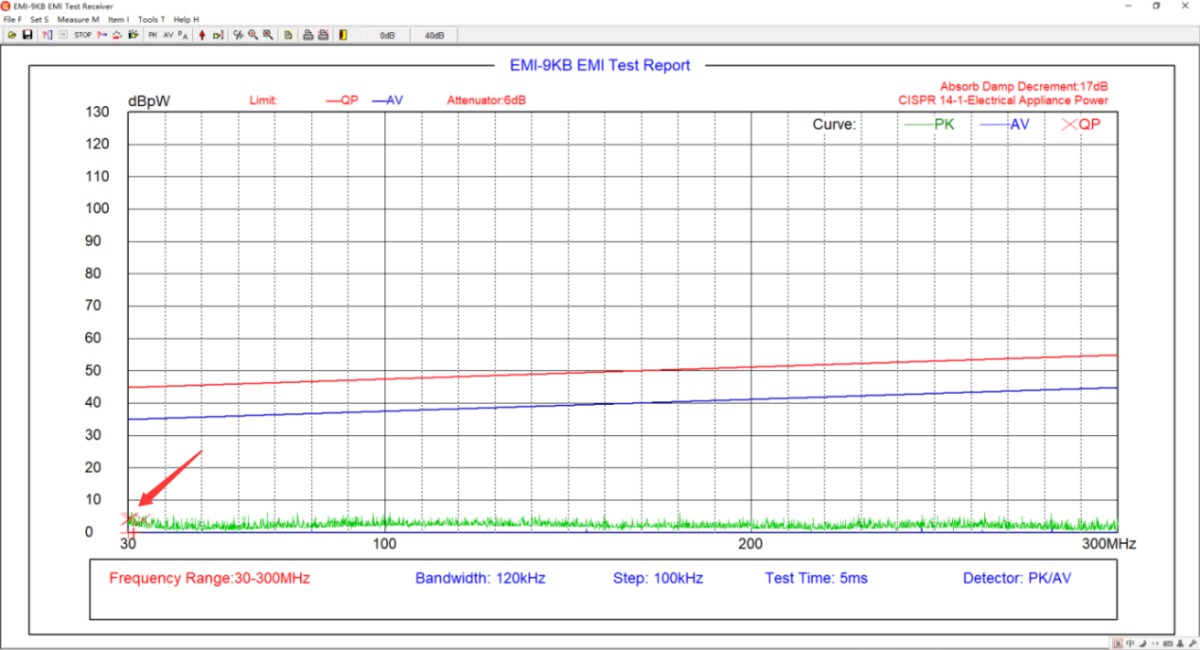
그림 6~7
6.6 Save and Print the Test Report
테스트 보고서를 저장하거나 인쇄하려면 4.2.1절을 참조하십시오.
6.7 Procedure for Shutting Down the Machine at the End of a Test
Ensure the equipment is in the “test stop” state → Disconnect the coaxial cable on the EMI-9KB receiver side → Turn off the EUT’s power → Turn off the receiver and the computer → Turn off the Isolation Transformer.
7. 장비의 일상 유지보수 및 관리
7.1 일상적인 유지보수
7.1.1 Absorbing Clamps
After each use, wipe the surface of the pliers with a dry, soft cloth to remove dust and stains; Do not use highly corrosive solvents such as gasoline, acetone, or thinners for cleaning. To remove stubborn stains, use a lint-free cloth dipped in a small amount of anhydrous ethanol to wipe the area quickly, then dry it immediately.
Check the latch and hinge of the pliers monthly to ensure they open and close smoothly; you may apply a small amount of silicone grease for lubrication. Inspect the N-type output connector, remove any oxidation, and cover it with a protective cap when not in use to prevent dust from entering.
Handle the equipment with care; do not drop or subject it to impact, to prevent the internal ferrite cores from shattering. Do not use the pliers to grip hard objects or apply excessive force when opening or closing them.
Do not disassemble the clamp body on your own. The internal magnetic ring and structural alignment have been calibrated before shipment; disassembly will result in a loss of testing accuracy.
7.1.2 동축 케이블 및 감쇠기
동축 케이블을 심하게 구부리거나, 밟거나, 무거운 물체로 압력을 가하지 마십시오. 보관할 때는 내부 도체가 손상되지 않도록 느슨하게 감아 두십시오.
감쇠기 및 커넥터와 같은 정밀 액세서리는 떨어뜨려 내부 손상을 방지하기 위해 조심스럽게 다루십시오.
7.2 Storage Specifications
7.2.1 저장 환경 요구 사항
Temperature: 5°C to 35°C; relative humidity: ≤65% RH; dry, dust-free environment free of corrosive gases.
7.2.2 장기 저장 작업
전원을 끄고 모든 케이블을 뽑으십시오. 장비를 청소하고 먼지 방지 필름으로 감싸십시오.
7.3 교정 주기 요구사항
측정 정확도와 장비의 작동 신뢰성을 보장하기 위해, 자격을 갖춘 제3자 계측 연구소에 정기적으로 보내 교정을 받는 것이 좋습니다. 권장 교정 주기는 12개월입니다. 사용자는 사용 빈도, 환경 조건 및 품질 시스템 요구 사항을 고려하여 구체적인 교정 주기를 결정할 수 있습니다.
8. 문제 해결 및 일반적인 문제 해결 방법
8.1 Absorbing Clamps
| 결함 증상 | 순서 |
| 흡입 집게가 부드럽게 열리고 닫히지 않으며, 잠금 장치가 단단히 고정되지 않습니다. | Clean the pivot shaft and apply a small amount of silicone grease for lubrication; remove any foreign objects from inside the jaws and ensure the magnetic ring is undamaged; verify that the diameter of the cable being tested is ≤20 mm, and replace it with a suitable cable. |
8.2 EMI-9KB 리시버
| 결함 증상 | 순서 |
| Various error messages appear while using the software, such as “The software cannot be opened” or “An error occurred during scanning.” | 컴퓨터에 관리자 계정으로 로그인했는지, 그리고 소프트웨어가 관리자 권한으로 실행되고 있는지 확인하십시오. |
| The software worked normally during the scan test, but crashed during the final test. | 최종 테스트는 스캔 테스트보다 통신 요구 사항이 더 엄격합니다. 반드시 당사 정품 통신 케이블만 사용하고 다른 통신 케이블이나 연장 코드는 사용하지 마십시오. 또한 데스크톱 컴퓨터 뒷면의 통신 포트를 사용하고 있는지 확인하십시오(노트북이나 데스크톱 컴퓨터 앞면의 USB 포트는 일반적으로 충분한 전력을 공급하지 못하여 통신에 영향을 줄 수 있습니다). 그래도 작동하지 않으면 다른 방법을 시도해 보십시오. RS232 컴퓨터에 포트를 연결하고 다음만 사용하십시오. RS232 통신용 케이블은 사용하지 마십시오. RS232USB 어댑터. |
| 검사 결과는 일반적으로 예상보다 낮거나 높습니다. | 소프트웨어 감쇠기 설정이 실제 조건과 일치하는지 확인하십시오. |
| 테스트 결과는 항상 배경 잡음에 가깝고, EMI 수신기는 어떤 신호도 감지할 수 없습니다. | 동축 케이블 연결 상태를 확인하고, 동축 케이블을 교체한 후 다시 시도해 보세요. |
| 과도하게 높은 배경 소음과 테스트 데이터의 상당한 변동 | 시스템 내 모든 장비에 절연 변압기가 사용되는지 확인하고, 접지 저항을 줄이기 위해 접지 시스템을 최적화하며, 실험실 내 다른 전기 장비를 끄거나 차폐실 내부에서 테스트를 수행하십시오. |