
 영어
영어 中文简体
中文简体 Русский
 Español
 Português
 Türkçe
 العربية
 Deutsch
 Polski
 Italiano
 Français
 한국어
한국어 ไทย
ไทย Tiếng Việt
 日本語
日本語





























EFT 면역 측정
사용자 설명서
적용 할 수있는 LISUN models: EFT-CLAMP、EFT-DESK、EFT61000-4,EFT61000-4-100A、EFT61000-4-32A、EFT61000-4ㅏ.EFT61000-4A-100A、EFT61000-4A-32A
1. 제품 개봉 및 기본 사용법 익히기
1.1 주요 기술 사양
| LISUN 모델 | EFT61000-4 | EFT61000-4A | EFT61000-4-32A | EFT61000-4A-32A | EFT61000-4-100A | EFT61000-4A-100A |
| Output Voltage | 0–5kV | 0–6kV | 0–5kV | 0–6kV | 0–5kV | 0–6kV |
| 펄스 주파수 | 0.1 kHz to 1200 kHz, continuously adjustable | |||||
| 펄스 극성 | Positive/Negative, Automatic Alternation Between Positive and Negative | |||||
| 내부 저항 | 50 Ω ±20%, 1000 Ω ±20% | |||||
| 펄스 상승 시간 | 5ns ±30% | |||||
| Pulse Width (at 50 Ω) | 50ns ±30% | |||||
| Pulse Width (at 1 kΩ) | 35ns ~ 150ns | |||||
| 펄스 트레인 기간 | 1ms ~ 1000ms | |||||
| Number of Pulse Strings | 1-255 | |||||
| 시험 시간 | 1 s–9999 s | |||||
| 기능 테스트 | Set the test mode or IEC class as desired | |||||
| 커플 링 및 디커플링 네트워크 | 내장형 16A, 3상/5선 | 내장형 32A, 3상/5선 | 외부 100A, 3상/5선 | |||
| 전원 공급 장치 | AC 220 V (110 V optional) ±10%, 50/60 Hz | |||||
1.2 Unboxing Inspection and Verification of Accessories
1.2.1 포장 해제 및 육안 검사
기기를 개봉할 때는 날카로운 도구로 케이스에 흠집이 나지 않도록 조심스럽게 다루십시오. 개봉 후에는 먼저 기기 외관을 검사하여 눈에 띄는 변형이나 찌그러짐이 없는지, 버튼이 손상되었거나 헐거워지지 않았는지 확인하십시오.
If you notice any damage or deformation to the equipment or accessories, do not turn on the power. Please contact us immediately.
1.2.2 호스트 컴퓨터 및 액세서리
Main Units: ① EFT61000-4 EFT Immunity Measurement; ② EFT-DESK Standard Test Bench; ③ EFT-CLAMP Capacitive Coupling Clamp.
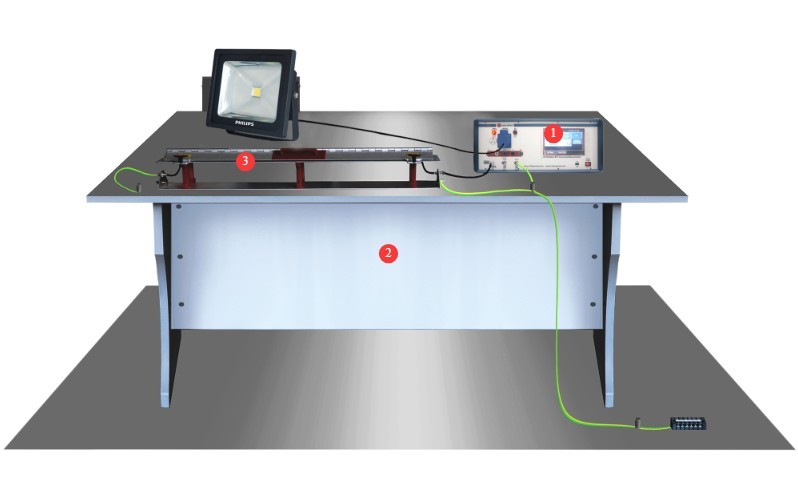
그림 1
Note: Items ② and ③ are optional.
The EFT-CLAMP Capacitive Coupling Clamp is used to test I/O lines.
Standard Accessories: ① Power cord; ② or ③ EUT power input cable (choose one);④ EUT power output, used to connect the EUT to the instrument’s front panel; ⑤ coaxial cable, used to connect to an external oscilloscope for waveform monitoring; ⑥ ground wire, used to connect to the PGND protective ground terminal; ⑦ discharge tube, used to check whether the instrument produces a pulse output in the event of a device malfunction.
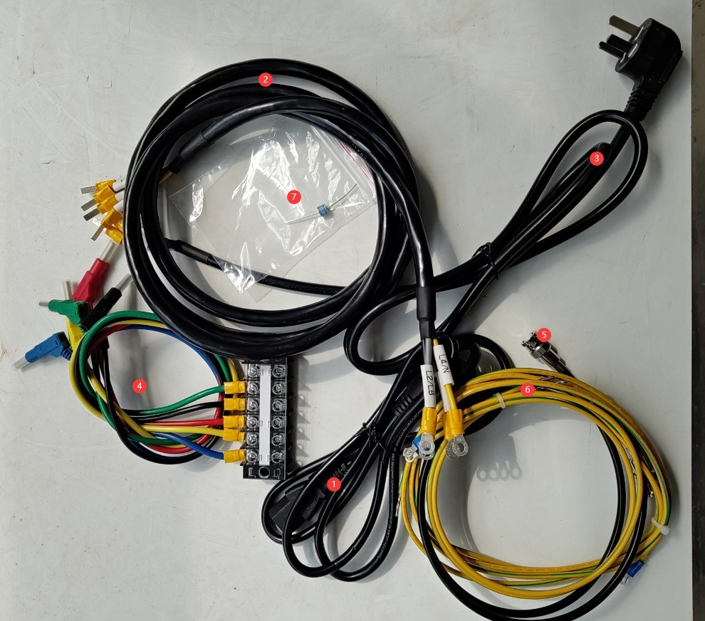
그림 2
Download links for the digital user manual, warranty card, and other documents have been sent to you via email. Please download them as soon as possible. If you missed the email, please feel free to contact us to request the download links again.
2. 안전상의 주의
2.1 Placement Guidelines
Place it on a stable work surface; avoid tilting or inverting it, and keep it away from sources of vibration;
The equipment must be placed at least 1000 mm away from walls and surrounding structures (such as other testing equipment and shelving) to facilitate maintenance; at least 2000 mm of space must be left in front of the equipment to ensure smooth operation, and there must be no obstructions in the surrounding area.
2.2 High-Voltage Safety Standards
2.2.1 보안 검색
전원 공급 장치가 장비와 호환되는지 확인하고, 전원 공급 장치가 제대로 접지되었는지 확인하며, 접지선에 손상이나 느슨함이 없는지 점검하십시오.
Grounding Requirements: The host unit’s protective grounding terminal (PGND) must be connected to the ground reference plane; the grounding resistance must be ≤4 Ω; the grounding cable must be securely connected, with no looseness or breaks;
The ground reference plane must be connected to the grounding metal plate and to the ground; all ground connections must have low impedance to prevent potential differences from occurring during discharge.
2.2.2 운영 절차에 대한 안전 요구 사항
작업자는 전문 교육을 이수하고 본 설명서 및 관련 표준을 숙지해야 합니다. 비전문가는 장비를 작동하거나 분해할 수 없습니다. 본 장비에는 고전압 회로가 포함되어 있으므로 덮개를 열면 감전 위험이 있습니다. 수리가 필요한 경우 제조업체의 기술 담당자에게 문의하십시오.
Once the equipment is powered on, do not touch the terminal blocks, cables, or the EUT;
작업자는 손이 건조하고 금속 장신구가 없는지 확인해야 하며, 작업 중에는 절연 장갑을 착용하는 것이 좋습니다.
During testing, unauthorized personnel are prohibited from remaining within 1 meter of the EUT to prevent accidental electric shock or interference from electrical discharges;
Before replacing the electrodes, you must first ensure that the high-voltage output has been turned off (the HV indicator light is off) and wait at least 5 minutes to ensure that the internal high-voltage capacitor is completely discharged;
Do not eat or drink during the test to prevent accidents caused by electric shocks;
여러 사람이 참여하는 경우, 역할과 책임을 명확하게 정의하고 오류를 방지하기 위해 테스트 시작 전에 서로 확인해야 합니다.
2.3 기타
본 설명서에 나와 있지 않은 사항에 대해서는 주의를 기울여 진행하시거나 당사에 문의해 주십시오.
3. 시험 전 준비 사항
3.1 Test Environment and Wiring for Power Cord Immunity Testing
3.1.1 Front of the Instrument
① Grounded metal plate, connected to ground via a conductor; ② Wooden test bench; ③ Grounded reference plane, connected to the grounded metal plate via a ground wire;④ Can be connected to the EUT; ⑤ Can be connected to the EUT; ⑥ Connect the protective ground terminal of the SGND signal line on the front panel of the instrument to the reference ground plane; ⑦ Insulated support; ⑧ EUT test specimen.
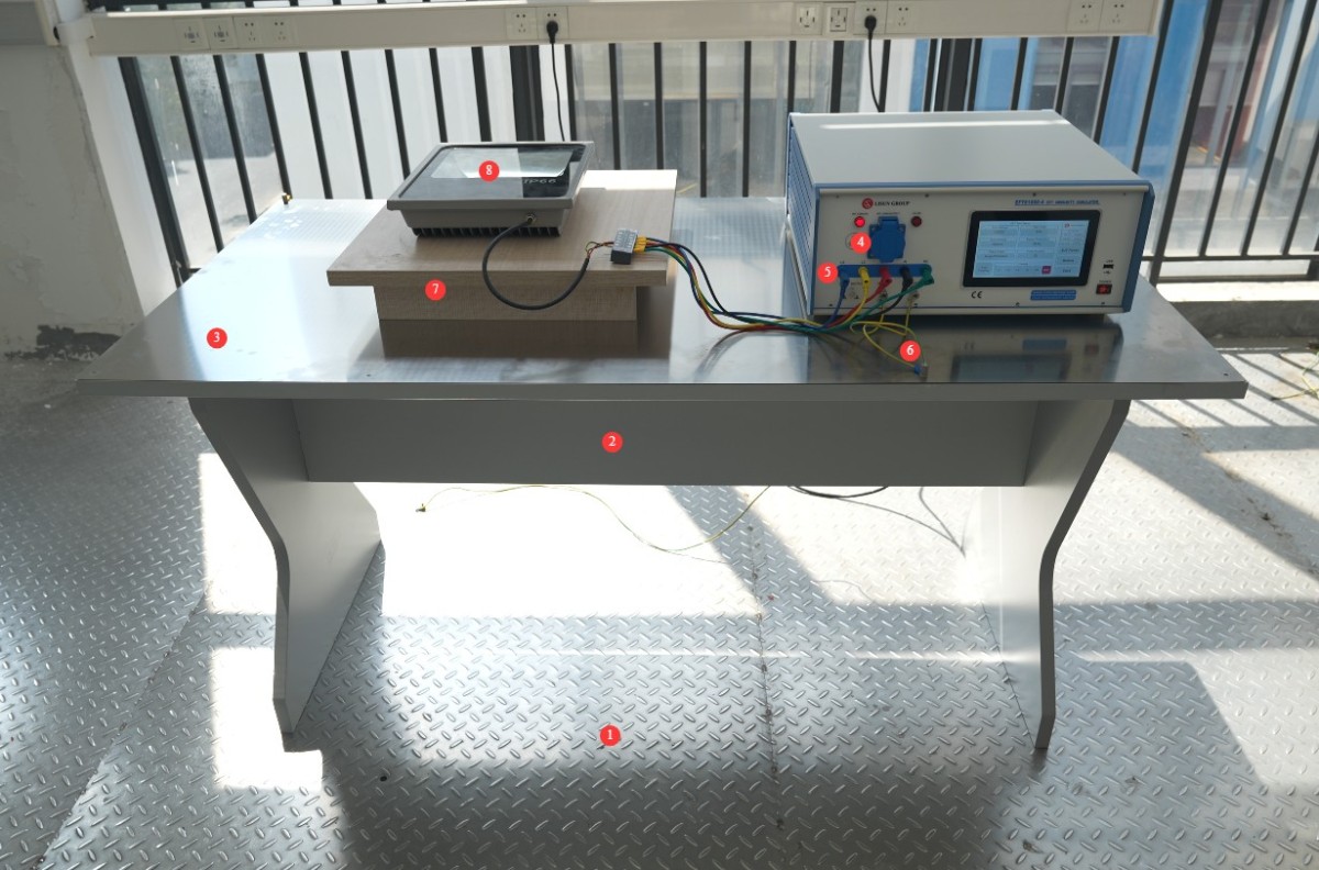
그림 3
The grounding reference plane must meet the following dimensions: thickness ≥ 0.25 mm; it must be large enough to accommodate the EUT, instruments, coupling devices, and all accessories; and it must extend 10 cm beyond the edges on all four sides.
The EUT must be placed on the grounded reference plane using an insulating support with a thickness of 10 cm, and the distance between the bottom of the EUT and the grounded reference plane must be strictly maintained at 10 cm.
The instrument (including the coupling network) shall be placed directly on the grounded reference plane, at a distance of ≥0.5 m from the EUT; the EUT shall be located at a distance of ≥0.5 m from conductive structures such as laboratory walls and anechoic chamber walls.
The length of the power and signal cables connecting the EUT to the test equipment shall be maintained at 0.5 m ± 0.05 m; if the EUT has a built-in, non-detachable cable longer than 0.5 m, the excess length shall be folded (avoiding the formation of a flat loop) and placed 10 cm above the ground reference plane.
3.1.2 Back of the Instrument
① Power cord; ② EUT power input cable—please connect the EUT to a suitable power source; ③ PGND protective ground terminal—please connect to a grounded metal plate.
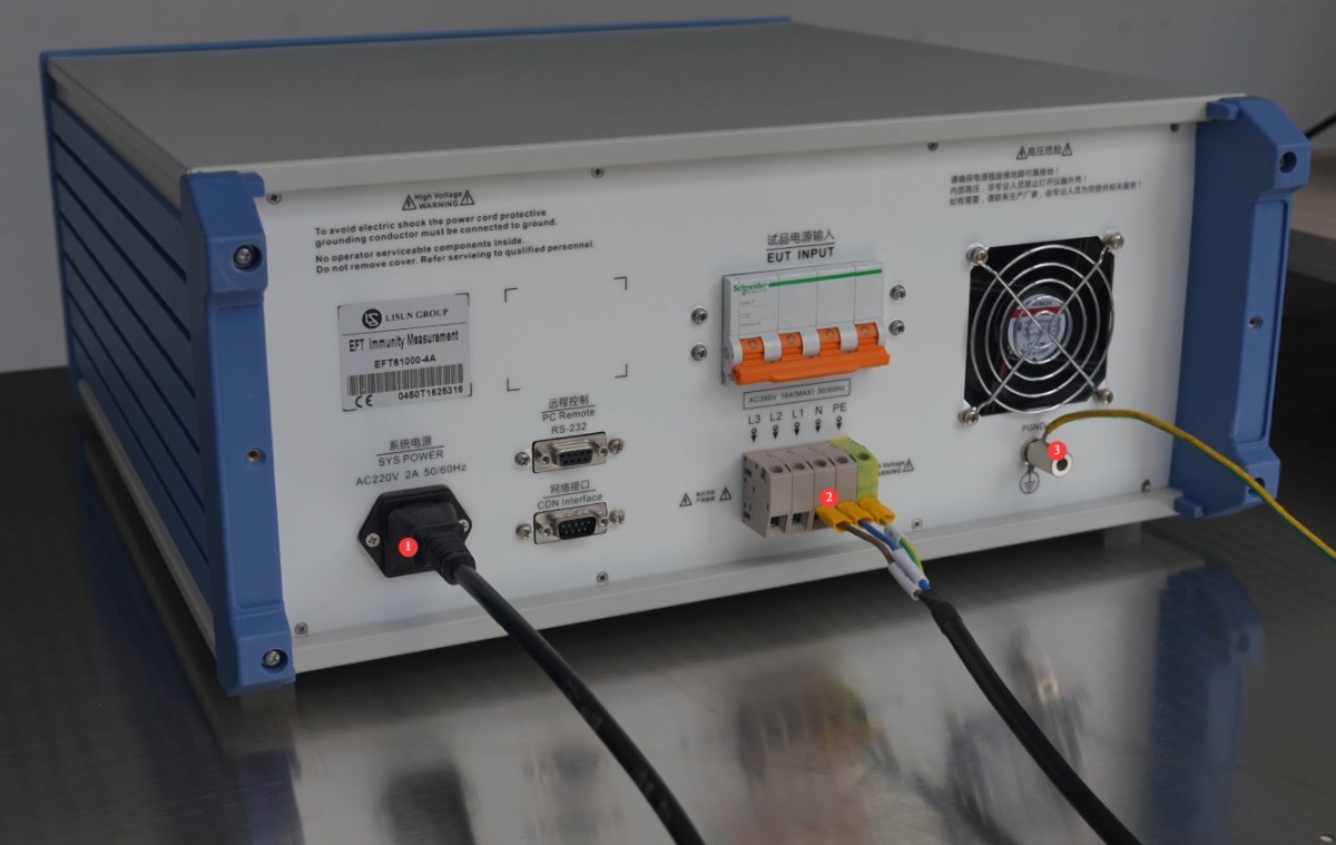
그림 4
3.2 Test Environment and Wiring for IO Signal Line Immunity Testing
Place the Capacitive Coupling Clamp on the ground reference plane. ① Connect the ground terminal of the Capacitive Coupling Clamp to the ground reference plane; ② Connect the Capacitive Coupling Clamp to the BNC connector on the instrument’s front panel via a coaxial cable; ③ Route the I/O cable through the Capacitive Coupling Clamp.
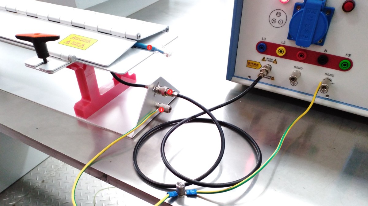
그림 5
Route the EUT’s I/O cables through the capacitive coupling clamp, with one end of each cable connected to the EUT and the other to the AE (auxiliary) device. Place the EUT and the AE device on 10-cm-thick insulated supports, respectively.
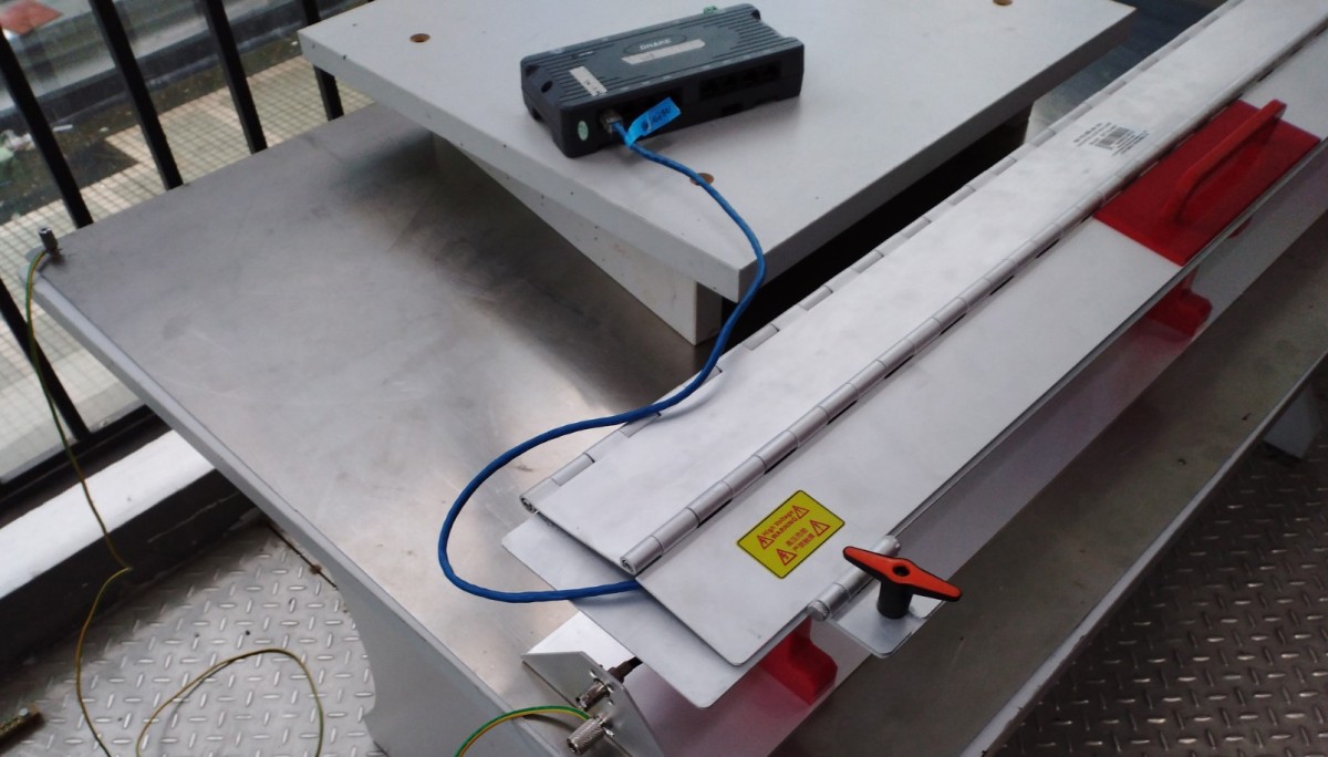
그림 6
The distance between the AE equipment and the EUT must be ≥0.5 m, and its power cord must be connected to the power supply network via a decoupling network to prevent impulse interference from being conducted to auxiliary equipment.
3.3 Confirmation of Test Parameters
| 매개 변수 이름 | 설정 범위 | Standard Requirements (GB/T 17626.4-2018) |
| 시험 전압 | 0.25–5/6 kV (open circuit) | Power Ports: Levels 1–4 (1 kV/2 kV/4 kV/6 kV); I/O Ports: 1 and 2 corresponding to the power ports |
| 시험 시간 | 1–9999초 | The standard test duration is 60 seconds; custom durations are available upon request. |
| 펄스 트레인 기간 | 1~1000밀리초 | The default value is 300 ms, but it can be modified according to the test plan. |
| 펄스 반복 주파수 | 0.1–1200kHz | Commonly used frequencies: 5 kHz, 100 kHz, 300 kHz |
| 위상 각 | 0–359°/Asynchronous | If there are no synchronization requirements, select “Asynchronous.” |
| 펄스 수 | 1-255 | The default is 75. The string length is calculated as (number of items – 1) / frequency of repetition. |
| 펄스 극성 | Positive/Negative/Alternating Positive and Negative | For routine testing, select “Alternating Positive and Negative” to cover all interference scenarios. |
3.4 Equipment Warm-up and Self-Test
Turn on the power switch on the front panel of the host; the device enters standby mode, the power indicator lights up, and the cooling fan starts.
Wait 5 minutes for the device to warm up, and check that the touchscreen is displaying normally and that there are no error messages.
4. 터치스크린 프로그램 소개
4.1 초기화면
① General Usage Notes (Features are still being developed; no action is required at this time); ② System Information Screen; ③ Switch Between Chinese and English; ④ EFT Test Screen.
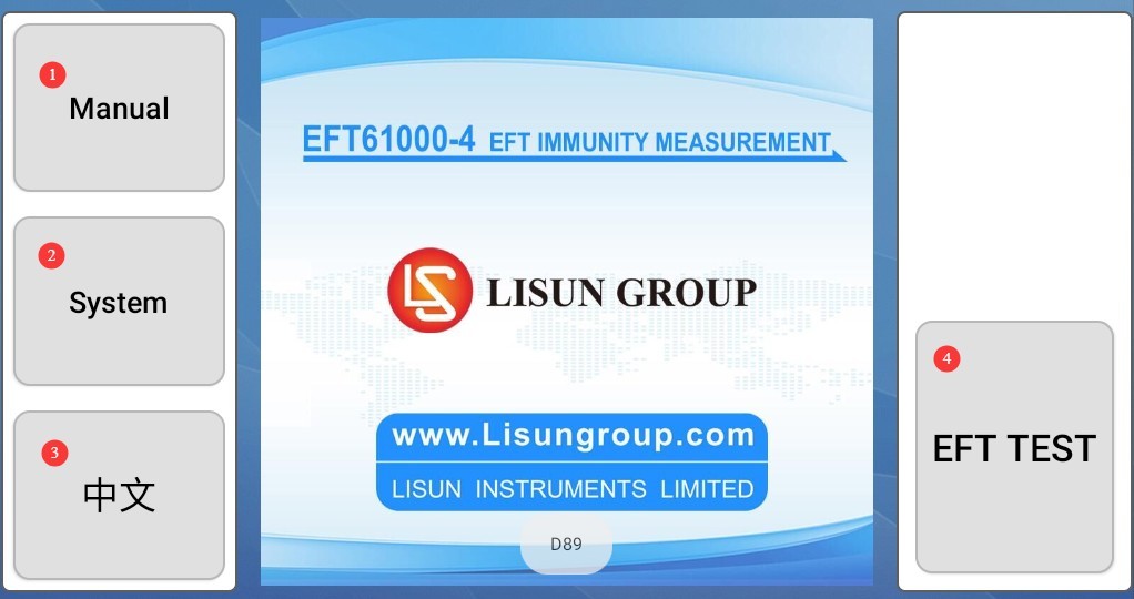
그림 7
4.2 System Information Screen
Test Logs: View or export historical test logs.
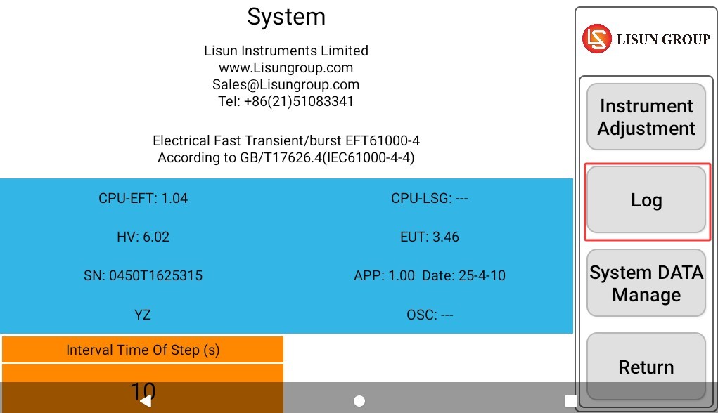
그림 8
4.3 EFT Test Interface
① Test voltage and polarity settings; ② Test duration settings; ③ Pulse train period settings; ④ Pulse repetition frequency settings; ⑤ Phase angle settings; ⑥ Number of pulses settings; ⑦ Automatic coupling option, allowing you to select the required coupling lines all at once;⑧ Manual selection of coupling lines; single or multiple selections are possible; ⑨ Display of the EUT’s current electrical parameters; ⑩ Click to turn the EUT power on or off; ⑪ Click to start or stop the test.
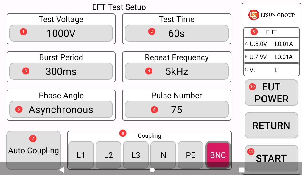
그림 9
Note: Power port coupling: Select any combination of “L1,” “L2,” “L3,” “N,” and “PE”; Signal port coupling: Select “BNC”; Automatic coupling: Applies interference in the system’s preset order (L1 → L2 → L3 → N → PE → combination), suitable for comprehensive testing.
5. Fast Transient and Burst (FTB) Test
5.1 운영 절차
If the EUT requires power, close the EUT power input switch on the back of the device.
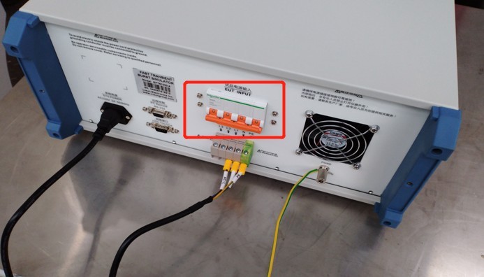
그림 10
Set all test parameters according to sections 3.3 and 4.3.
Click “EUT POWER” to turn on the EUT power supply.
Click “START” to begin the test.
5.2 Determining Whether the EUT Has Passed the Test
| 기준 수준 | Definition of Standards | 간단한 설명 | 준수 선언문 |
| Category A (Highest Requirements) | Performs normally within the limits specified by the manufacturer, the client, or the purchaser | During and after the test, the EUT’s functionality and performance were completely unaffected, with no abnormalities observed. | Fully meets the requirements; passed the test |
| 카테고리 B | A temporary loss or reduction in function or performance that resolves on its own once the disturbance ceases, without requiring operator intervention | Temporary malfunctions (such as stuttering or brief data loss) may occur during the test, but normal operation will resume immediately after the pulse stops. | Generally considered acceptable and suitable for most non-critical equipment |
| 카테고리 C | A temporary loss or reduction in functionality or performance that requires operator intervention to restore (e.g., restart, reset, reconfiguration) | After the test, the EUT was unable to return to normal on its own and required manual intervention to restore functionality. | This is generally considered nonconforming, unless otherwise specified in the product standard. |
| 카테고리 D | Irreversible loss of functionality or reduced performance due to hardware or software damage, or data loss | The EUT has suffered a permanent failure, such as hardware damage, a software crash, or the loss of critical data that cannot be recovered. | Completely unsatisfactory; test failed |
6. 테스트 후 절차
6.1 Test Stopped
If the EUT is visibly damaged during the test, immediately tap “Stop Test” on the touchscreen, then tap “EUT Power” to turn off the EUT’s power.
If no abnormalities occur during the test, wait for the pulse test to complete automatically, then click “EUT Power” to turn off the EUT’s power.
Turn off the EUT input power supply switch on the back of the unit.
Wait 5 minutes to ensure that the high-voltage capacitors inside the host unit have fully discharged, then replace the EUT for testing, or turn off the host unit’s power.
6.2 Post-Test Cleanup and Tidying Up
Clean the test area and wipe it down with a dry cloth; do not use alcohol or corrosive cleaning agents.
Pulse testing is a destructive test; it does not automatically generate a test report, but the device automatically saves the test data. You can go to “System Information,” click “Test Log,” and export the corresponding test data to a USB flash drive via the USB port. The exported file is in TXT text format.
6.3 장비 보관
6.3.1 Short-Term Storage Requirements
If the equipment is used on a daily basis, no further action is required after each test is completed and the equipment has been cleaned.
6.3.2 장기 보관 요건
기기를 장기간(한 달 이상) 사용하지 않을 경우 모든 케이블을 분리하고 먼지가 쌓이는 것을 방지하기 위해 먼지 덮개로 기기를 덮어주십시오.
The device should be powered on once a month for just half an hour to prevent the aging of electrical components (such as capacitors and contactors).
7. 문제 해결 및 일반적인 문제 해결 방법
7.1 The device won’t turn on
Symptom: After turning on the power switch, the device does not respond (the indicator light does not come on, and the fan does not spin).
Possible causes: ① The power cord is not properly connected or is damaged; ② Abnormal supply voltage; ③ A blown fuse; ④ A burned-out varistor (MOV).
Solution: Ensure the power cord is intact and securely connected. Power supply issues—such as unstable voltage, excessively high voltage, or harmonic interference—can cause the fuse or varistor to burn out. We recommend using a regulated, clean sine-wave AC power supply to power the device. Replace the fuse or varistor with one of the same type.
The figure below shows the location of the fuse:
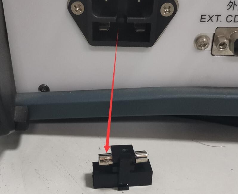
그림 39
The following figure shows the location of the varistor (MOV) inside the filtered power supply:
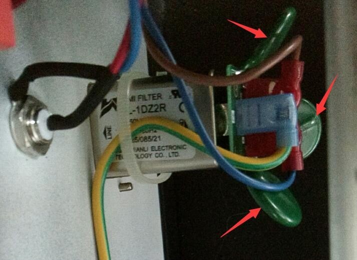
그림 40
7.2 Automatic Device Restart
Symptom: The device automatically restarts during pulse output.
Possible cause: The ground wire is not connected properly.
Solution: Refer to Section 2.2.1. Connect the PGND grounding terminal on the back of the host to ground, and ensure that the grounding resistance is ≤4Ω. Otherwise, high voltage may not be safely dissipated, causing the device to automatically restart.
7.3 Pulse Phase Angle Test Failed
Symptom: The synchronization phase angle has been set, but the pulse test is not being performed according to the corresponding phase angle.
Possible cause: The EUT power supply is not turned on.
Procedure: The EUT must be powered by an AC source, and the EUT must be turned on during testing so that the pulse generator can detect the EUT’s power supply waveform and perform pulse testing according to the set phase angle.