
 영어
영어 中文简体
中文简体 Русский
 Español
 Português
 Türkçe
 العربية
 Deutsch
 Polski
 Italiano
 Français
 한국어
한국어 ไทย
ไทย Tiếng Việt
 日本語
日本語





























자동차 과도 현상 내성 발생기
사용자 설명서
적용 할 수있는 LISUN 모델: EMS-ISO7637-P123-80V100A、EMS-ISO7637-P123-80V30A、EMS-ISO7637-P123-80V50A、EMS-ISO7637-P1235-80V100A、EMS-ISO7637-P1235-80V30A、EMS-ISO7637-P1235-80V50A、EMS-ISO7637-P5-80V100A、EMS-ISO7637-P5-80V30A、EMS-ISO7637-P5-80V50A
1. 장비에 대한 기본 이해
1.1 모델 분류
| LISUN 모델 | EMS-ISO7637-P1235-80V30A | EMS-ISO7637-P123-80V30A | EMS-ISO7637-P5-80V30A |
|---|---|---|---|
| 제품명 | 자동차 과도 현상 내성 발생기 | Automotive Electronic Load Dump Simulator | |
| DUT 전압 및 전류 | Built-in Coupling Decoupling Network: 80 V/30 A (optional: 80 V/50 A and 80 V/100 A) | ||
| 제어 시스템 | 10.1-inch Chinese-English Android Capacitive Touchscreen Display + Supports Remote Control via PC Software | ||
| 테스트 파형 | Pulse 1, Pulse 2a, Pulse 3a, Pulse 3b, Pulse 5a, Pulse 5b | Pulse 1, Pulse 2a, Pulse 3a, Pulse 3b | Pulse 5a, Pulse 5b |
| 기타 | Supports immunity testing for 12V/24V automotive electronic systems; features built-in standard test parameters that can be accessed with a single click, and supports user-defined parameters | ||
1.2 적용 기준
| 표준 번호 | 이름 |
|---|---|
| ISO 7637-2 : 2021 | Road Vehicles—Electrical Disturbances from Conduction and Coupling—Part 2: Electrical Transients Conduced Along Supply Lines Only |
| ISO 7637-3 : 2016 | Road Vehicles—Electrical Disturbances from Conduction and Coupling—Part 3: Electrical Transient Transmission by Capacitive and Inductive Coupling via Lines Other Than Supply Lines |
| ISO 16750-2 : 2023 | 도로 차량 - 전기 및 전자 장비의 환경 조건 및 시험 - 제2부: 전기 부하 |
1.3 응용 프로그램 시나리오
The EMS-ISO7637 Automotive Transient Immunity Generator (also known as the Automotive Electronic Immunity Test System) is a professional test instrument independently developed by LISUN. It is designed to simulate various typical electromagnetic disturbances generated during normal vehicle operation, as well as changes in the vehicle’s onboard power supply that occur during vehicle startup, the switching of electronic devices, and battery charging and discharging. The waveforms generated by the equipment comply with the ISO 7637 series of international standards and meet the requirements of most automotive manufacturers for in-vehicle electronic immunity testing.
Applications include: conducted immunity testing of electronic components such as automotive ECUs, sensors, and controllers; verification of electromagnetic compatibility (EMC) performance for automotive components prior to shipment; validation and optimization of circuit protection solutions during the R& D phase; and compliance testing by third-party testing laboratories.
2. 사용상의 주의
2.1 환경 요구 사항
Ambient temperature: 23 °C ± 5 °C; relative humidity: 45–75%, non-condensing; altitude: ≤2000 m; no strong vibrations or electromagnetic interference in the surrounding area; use of the equipment in dusty or flammable and explosive environments is strictly prohibited.
2.2 전원 공급 장치 요구 사항
입력 전원: AC 220V ±10%, 50Hz; 입력 전력: 1kW 이하; 전원은 접지되어야 하며, 접지 저항은 1Ω 이하이어야 합니다. 전력망 변동이 테스트 정확도에 영향을 미치는 것을 방지하기 위해 전압 안정형 전원 공급 장치를 사용하는 것이 좋습니다.
2.3 배선 원리
고전류 조건에서 과열을 방지하기 위해 지정된 전선 굵기의 전원 케이블을 사용하십시오. 테스트 케이블은 가능한 한 짧게 유지하고 병렬로 배선하여 기생 파라미터의 영향을 최소화하십시오. DUT(테스트 대상 장치)의 외함이 장비의 보호 접지에 안정적으로 연결되어 있는지 확인하십시오. 또한 신호 케이블과 전원 케이블을 분리하여 배선하여 상호 간섭을 방지하십시오.
2.4 운영 안전 지침
절연 보호 장비를 착용하십시오. 테스트 전에 모든 연결부가 단단히 고정되어 있고 노출된 도체가 없는지 확인하십시오. 아크 화상을 방지하기 위해 테스트 중에는 테스트 케이블을 꽂거나 뽑지 마십시오. 펄스가 출력되는 동안 DUT 또는 테스트 장치를 만지지 마십시오. 이상한 소음이 들리거나, 이상한 냄새가 나거나, 연기가 나는 경우 즉시 전원을 차단하십시오. 장시간 연속 테스트 시에는 장비의 열 방출을 위해 적절한 환기가 이루어지도록 하십시오.
3. 장비 개요 및 배선
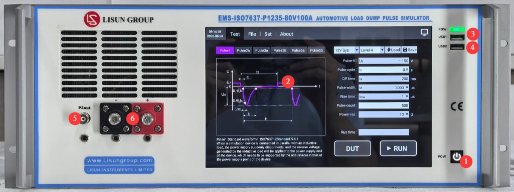
3.1 전면 패널
그림 3-1를 참조하세요.
| 번호 | 주의 사항 |
|---|---|
| ① | 기기 전원 스위치: 짧게 누르면 켜지고, 길게 누르면 꺼집니다. |
| ② | 10.1인치 정전식 터치스크린 |
| ③ | USB1 포트: 사용 대상 LISUN 엔지니어들이 장치 디버깅을 위해 사용하는 기능이며, 사용자들은 사용할 필요가 없습니다. |
| ④ | USB 2.0 포트는 마우스를 연결하여 터치스크린을 제어하거나, USB 플래시 드라이브를 연결하여 소프트웨어를 업그레이드하거나 데이터베이스 파일을 업데이트하는 데 사용할 수 있습니다. |
| ⑤ | BNC coaxial connector, used to connect auxiliary devices such as ICC, DCC, CCC (if any), or to connect an external oscilloscope to view BNC-coupled waveforms |
| ⑥ | DUT power cable connector, used to connect the DUT; observe the polarity |
3.2 후면 패널
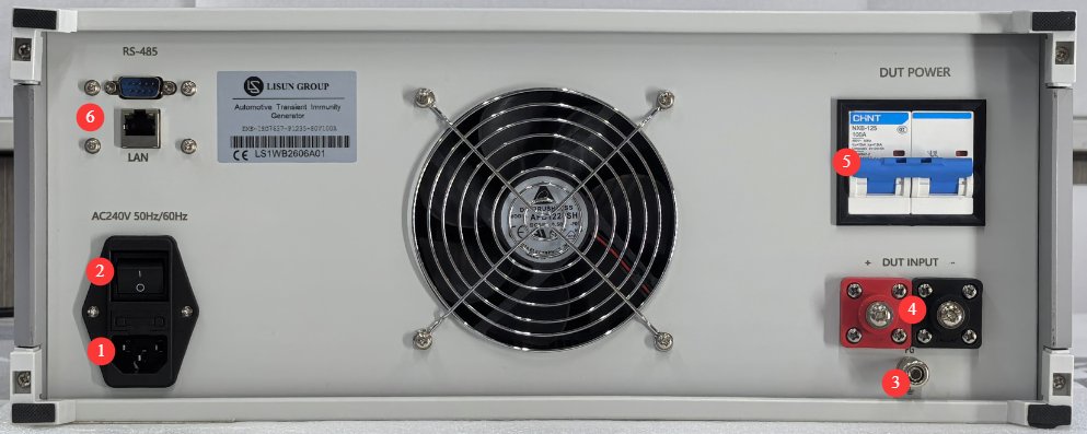
그림 3-2를 참조하세요.
| 번호 | 주의 사항 |
|---|---|
| ① | 전원 코드 소켓 및 퓨즈; 입력 전원 공급 장치가 제대로 접지되었는지 확인하십시오. |
| ② | 회로 차단기, 장비용 주 전원 입력 스위치 |
| ③ | Protective grounding terminal: If the input power supply does not have a reliable ground connection, a separate ground wire must be used to connect it to the ground. |
| ④ | DUT 전원 입력 커넥터: DUT에는 적합한 외부 전원 공급 장치가 제공되어야 합니다. 다음 제품을 사용할 수 있습니다. LISUNLIS-APS 시리즈 4사분면 전원 공급 장치 또는 DUT에 적합한 다른 DC 정류 전원 공급 장치를 사용하십시오. 극성에 주의하십시오. |
| ⑤ | DUT 전원 스위치 |
| ⑥ | RS485 인터페이스/LAN 포트를 통해 컴퓨터에 연결하여 호스트 소프트웨어(백업용)를 사용할 수 있습니다. 호스트 소프트웨어는 터치스크린과 동일한 기능을 제공합니다. 필요한 경우 문의해 주십시오. |
3.3 액세서리 소개
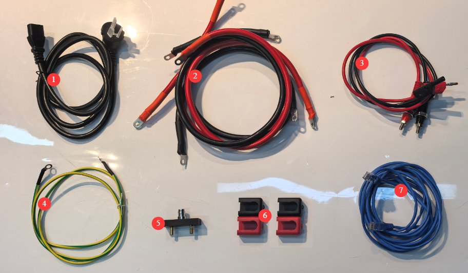
그림 3-3를 참조하세요.
| 번호 | 주의 사항 |
|---|---|
| ① | 전원 코드 |
| ② | DUT 전원 공급 장치 입력 및 출력 케이블 |
| ③ | The slim-profile output cable can be used to connect to LISUN’s calibration resistor, the LIS-CAR. |
| ④ | 접지선 |
| ⑤ | BNC adapter, used to connect to an external oscilloscope to view power line-coupled waveforms; be sure to observe the correct polarity when using it. |
| ⑥ | Insulation Protective Covers for DUT Input and Output Power Cables |
| ⑦ | Ethernet cable, used to connect a computer for use with host software |
4. 터치스크린 프로그램 소개
4.1 테스트 인터페이스
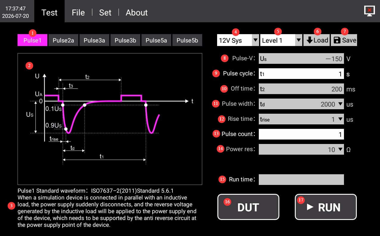
4.1.1 The Pulse 1 Interface
그림 4-1를 참조하세요.
| 번호 | 주의 사항 |
|---|---|
| ① | Waveform Selection: Click to select “Pulse 1” |
| ② | Schematic Diagram of Pulse 1 Waveform |
| ③ | Pulse 1 Standard Source and Test Instructions |
| ④ | Electrical System: Optional built-in 12V/24V system waveform parameters; custom parameters are also available. |
| ⑤ | Severity Levels: Select the appropriate severity level for each waveform as specified in the standard, as needed. |
| ⑥ | Load the test parameters saved by the device; this is generally not necessary. If you have previously customized parameters, you can load them. |
| ⑦ | Save the current test parameters. If you have custom parameters, you can click to save the current custom parameters to the device. You can manage them in the Files interface. |
| ⑧ | Pulse voltage: The built-in system waveform parameters have been set according to the standard and cannot be modified. When configuring custom parameters, you can set the pulse peak voltage Us. |
| ⑨ | Pulse Period: You can set the period of a single pulse; unless otherwise specified, use the default value. |
| ⑩ | Power-off time: the duration for which power to the 12V/24V system is disconnected. The built-in system waveform parameters have been set according to the standard and cannot be modified. These parameters can be set when configuring custom settings. |
| ⑪ | Pulse width: The built-in system waveform parameters are set according to the standard and cannot be modified. When configuring custom parameters, you can select the width of a single pulse from among 9 options ranging from 50 us to 2 ms. |
| ⑫ | For the rise time, the built-in system waveform parameters have been set according to the standard and cannot be modified. When configuring custom parameters, you can select the rise time for Pulse 1 from the options 1 us or 3 us. |
| ⑬ | Number of Pulses: Sets the number of pulses to be output during this operation. Unless otherwise specified, use the default value. |
| ⑭ | Power supply internal resistance: The built-in system waveform parameters have been set according to the standard and cannot be modified. When configuring custom parameters, you can select the internal resistance of the pulse source from the following options: 2 Ω, 4 Ω, 10 Ω, 30 Ω, 50 Ω, 60 Ω, and 100 Ω. |
| ⑮ | 실행 시간은 자동으로 표시되고 계산됩니다. 테스트가 시작되면 진행률 표시줄이 나타나 테스트 진행 상황을 보여줍니다. |
| ⑯ | DUT: Click to turn on the DUT power; click again to turn it off. |
| ⑰ | 실행: 파형 및 기타 매개변수를 선택한 후 이 버튼을 클릭하여 테스트를 시작하십시오. 테스트 중에는 진행률 표시줄이 1초마다 업데이트되어 테스트가 완료될 때까지 현재 진행 상황을 보여줍니다. 테스트 도중 이 버튼을 다시 클릭하면 현재 테스트가 중지됩니다. |
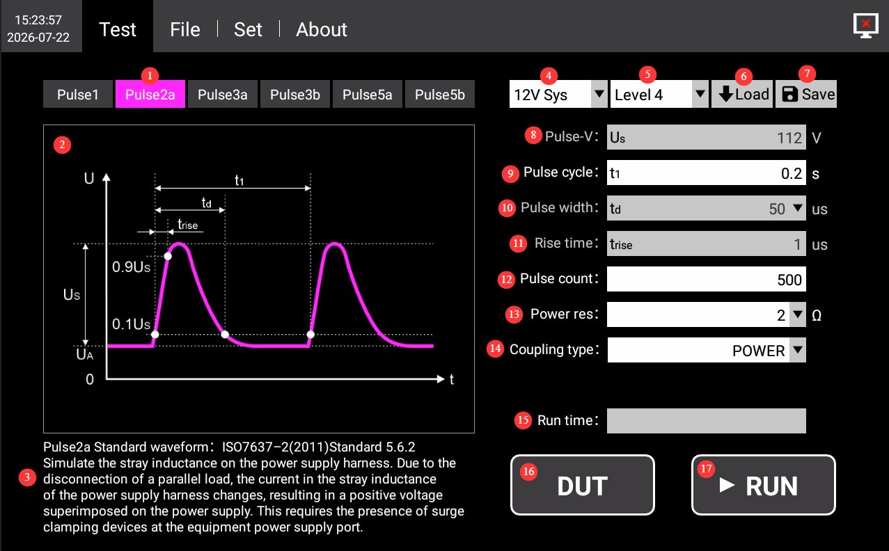
4.1.2 Pulse 2a Interface
그림 4-2를 참조하세요.
| 번호 | 주의 사항 |
|---|---|
| ① | Waveform Selection: Click to select Pulse 2a |
| ② | Pulse 2a Waveform Diagram |
| ③ | Pulse 2a Reference Sources and Test Instructions |
| ④ | Electrical System: Optional built-in 12V/24V system waveform parameters; custom parameters are also available. |
| ⑤ | Severity Levels: Select the appropriate severity level for each waveform as specified in the standard, as needed. |
| ⑥ | Load the test parameters saved by the device; this is generally not necessary. If you have previously customized parameters, you can load them. |
| ⑦ | Save the current test parameters. If you have custom parameters, you can click to save them to the device. You can manage them in the Files interface. |
| ⑧ | Pulse voltage: The built-in system waveform parameters have been set according to the standard and cannot be modified. When configuring custom parameters, you can set the pulse peak voltage Us. |
| ⑨ | Pulse Period: You can set the period for a single pulse; unless otherwise specified, use the default value. |
| ⑩ | Pulse width: The built-in system waveform parameters are preconfigured according to the standard and cannot be modified. When configuring custom parameters, you can select the width of a single pulse from among 9 options ranging from 50 us to 2 ms. |
| ⑪ | For the rise time, the built-in system waveform parameters have been set according to the standard and cannot be modified. When configuring custom parameters, you can set the pulse rise time. |
| ⑫ | Number of Pulses: Set the number of pulses to be output during this operation. Unless otherwise specified, use the default value. |
| ⑬ | The power supply’s internal resistance and the built-in system waveform parameters have been set according to the standard and cannot be modified. The power supply’s internal resistance can be modified when configuring custom parameters. |
| ⑭ | Coupling methods: Choose between power line output or BNC coaxial connector output. The coaxial output supports ICC (requires LISUN’s LIS-BCP110 ICC Current Injection Probe and LIS-CCF500 ICC High-Current Injection Probe) and DCC (requires LISUN’s DCC-100 DCC Coupling Capacitor). |
| ⑮ | 실행 시간은 자동으로 표시되고 계산됩니다. 테스트가 시작되면 진행률 표시줄이 나타나 테스트 진행 상황을 보여줍니다. |
| ⑯ | DUT: Click to turn on the DUT power; click again to turn it off. |
| ⑰ | 실행: 파형 및 기타 매개변수를 선택한 후 이 버튼을 클릭하여 테스트를 시작하십시오. 테스트 중에는 진행률 표시줄이 1초마다 업데이트되어 테스트가 완료될 때까지 현재 진행 상황을 보여줍니다. 테스트 도중 이 버튼을 다시 클릭하면 현재 테스트가 중지됩니다. |
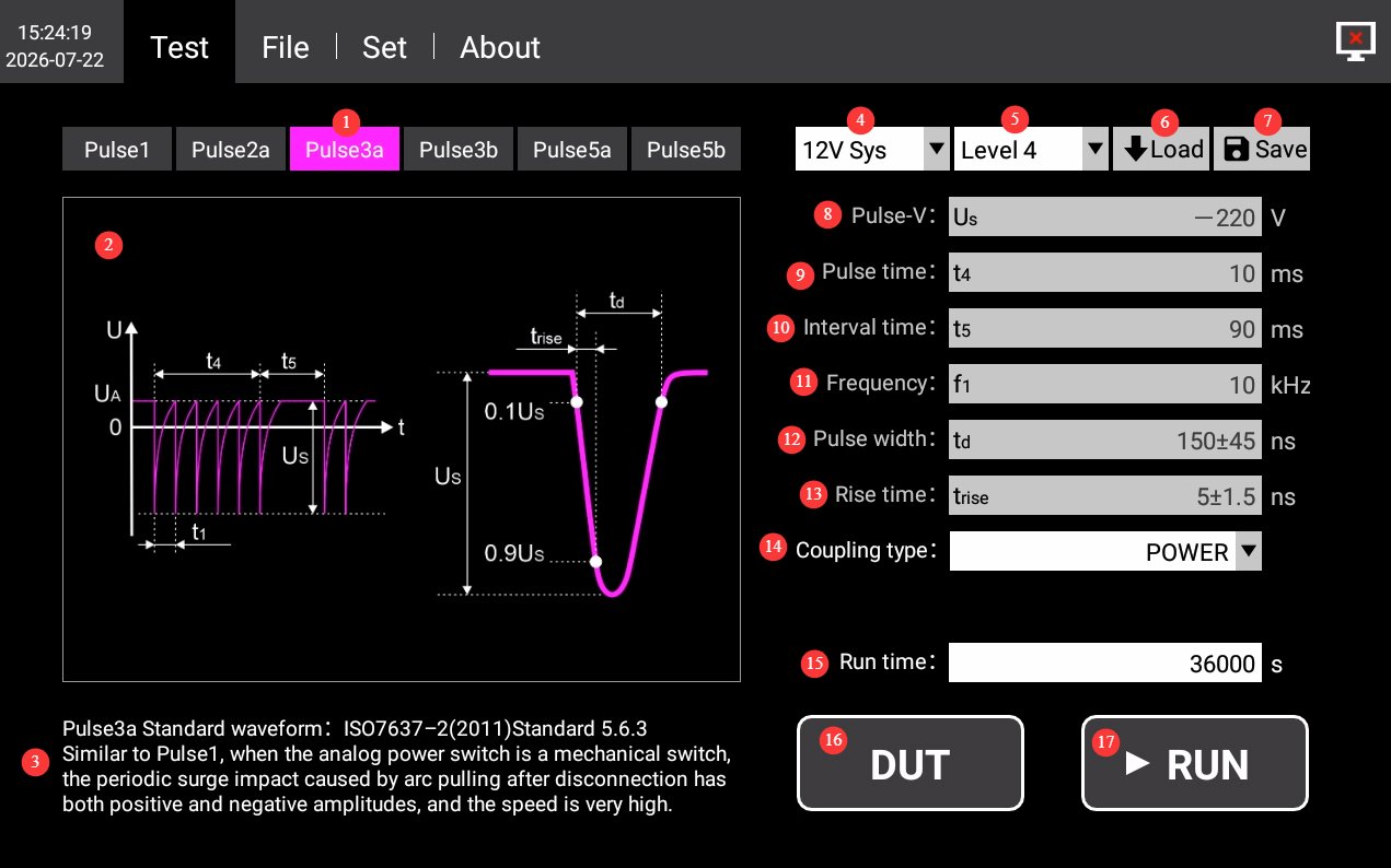
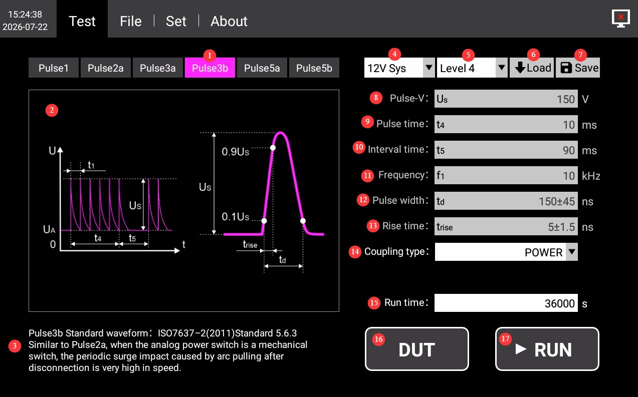
4.1.3 Pulse 3a/3b Interface
그림 4-3와 4-4을 참조하십시오.
| 번호 | 주의 사항 |
|---|---|
| ① | Waveform Selection: Click to select Pulse 3a/3b |
| ② | Schematic Diagram of Pulse 3a/3b Waveforms |
| ③ | Pulse 3a/3b Standards Sources and Test Instructions |
| ④ | Electrical System: Optional built-in 12V/24V system waveform parameters; custom parameters are also available. |
| ⑤ | Severity Levels: Select the appropriate severity level for each waveform as specified in the standard, as needed. |
| ⑥ | Load the test parameters saved by the device; this is generally not necessary. If you have previously customized parameters, you can retrieve them. |
| ⑦ | Save the current test parameters. If you have custom parameters, you can click to save them to the device. You can manage them in the Files interface. |
| ⑧ | Pulse voltage: The built-in system waveform parameters have been set according to the standard and cannot be modified. When configuring custom parameters, you can set the pulse peak voltage Us. |
| ⑨ | Pulse duration: The built-in system waveform parameters are already set according to the standard and cannot be modified. When configuring custom parameters, you can set the duration of the pulse group. |
| ⑩ | Interval Time: The built-in system waveform parameters have been set according to the standard and cannot be modified. When configuring custom parameters, you can set the interval time between pulse groups. |
| ⑪ | Pulse frequency: The built-in system waveform parameters are already set according to the standard and cannot be modified. When configuring custom parameters, you can set the frequency of the output pulses within a pulse group. |
| ⑫ | Pulse width: The built-in system waveform parameters are already set according to the standard and cannot be modified. When configuring custom parameters, you can set the pulse group width. |
| ⑬ | For the rise time, the built-in system waveform parameters have been set according to the standard and cannot be modified. The pulse rise time can be set when configuring custom parameters. |
| ⑭ | Coupling methods: You can choose between power cord output or BNC coaxial connector output. The coaxial output supports two coupling methods: CCC (requires LISUN의 VFTC capacitive coupling clamp) and DCC (requires LISUN’s DCC-100 DCC coupling capacitor). |
| ⑮ | Runtime: Configurable; the standard minimum test duration is 3600 seconds. |
| ⑯ | DUT: 클릭하여 DUT의 전원을 켜고, 다시 클릭하여 전원을 끄십시오. |
| ⑰ | 실행: 파형 및 기타 매개변수를 선택한 후 이 버튼을 클릭하여 테스트를 시작하십시오. 테스트 중에는 진행률 표시줄이 1초마다 업데이트되어 테스트가 완료될 때까지 현재 진행 상황을 보여줍니다. 테스트 도중 이 버튼을 다시 클릭하면 현재 테스트가 중지됩니다. |
4.1.4 Pulse 5a/5b Interface
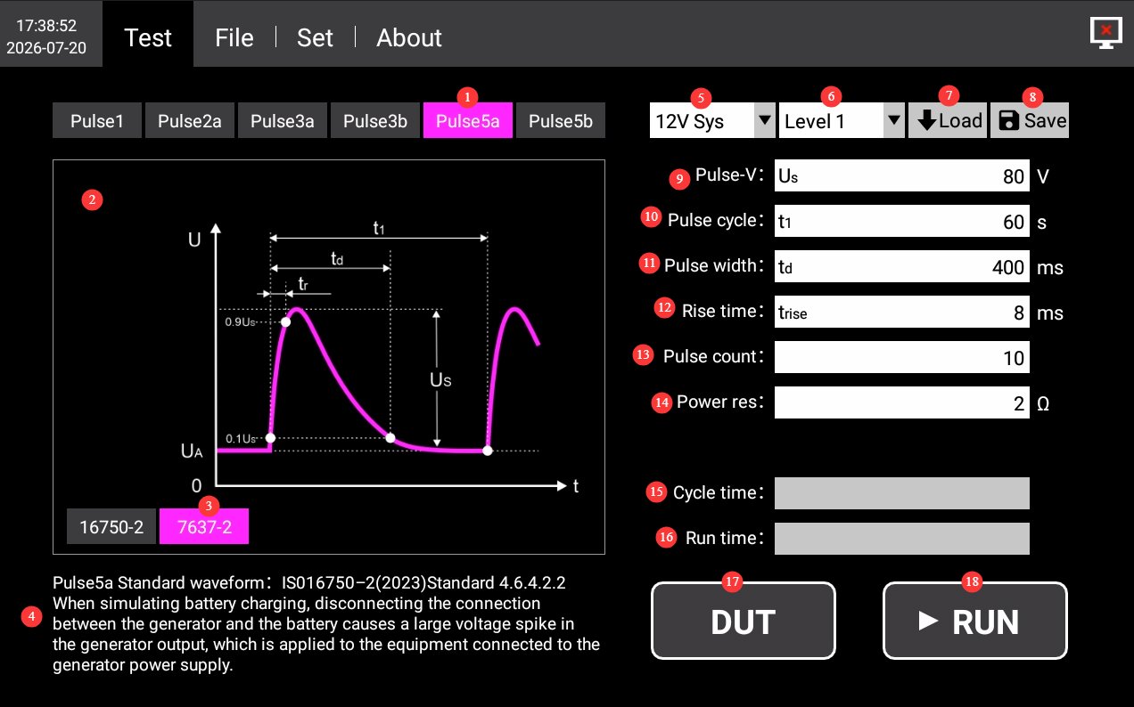
4.1.4.1 ISO 7637-2
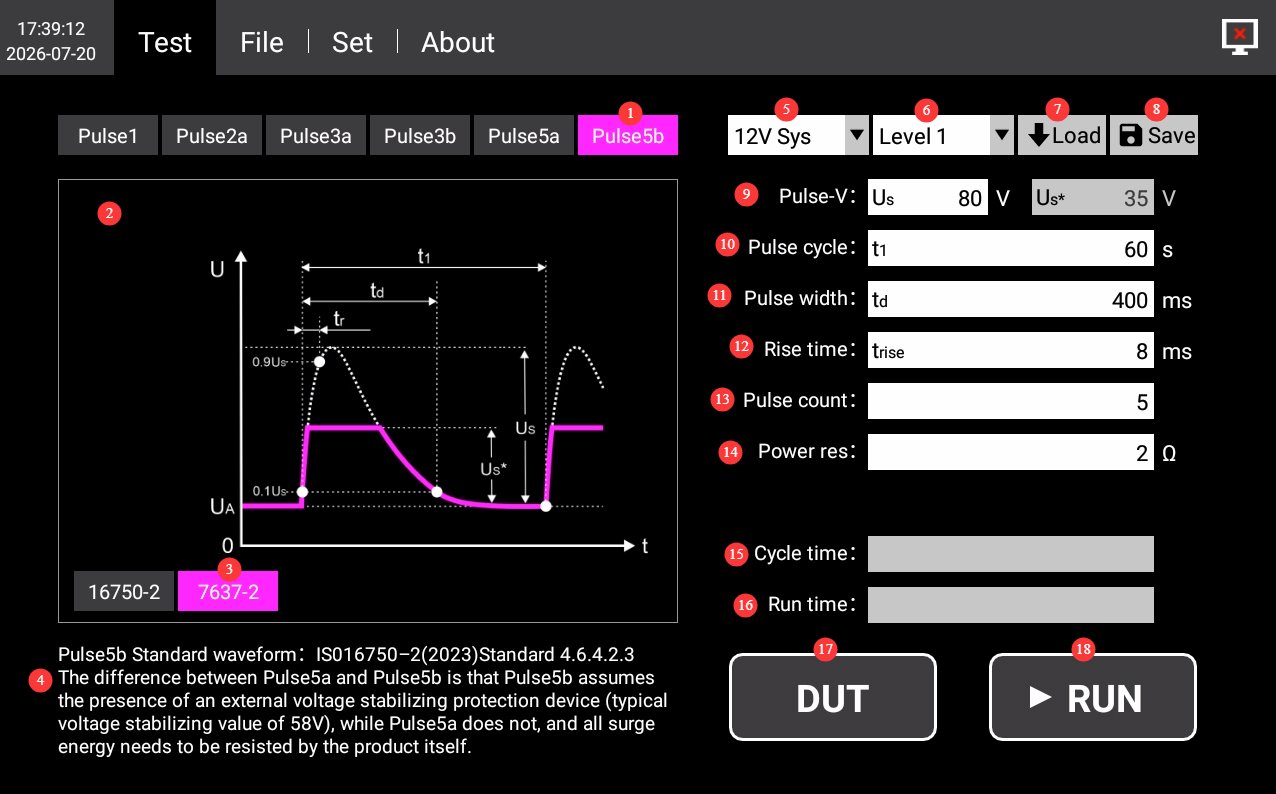
그림 4-5와 4-6을 참조하십시오.
| 번호 | 주의 사항 |
|---|---|
| ① | Waveform Selection: Click to select Pulse 5a/5b |
| ② | Schematic Diagram of Pulse 5a/5b Waveforms |
| ③ | Select the ISO 7637-2 standard |
| ④ | Pulse 5a/5b Standard Sources and Test Instructions |
| ⑤ | Electrical System: Optional built-in 12V/24V system waveform parameters; custom parameters are also available. |
| ⑥ | Severity Levels: Select the appropriate severity level for each waveform as specified in the standard, as needed. |
| ⑦ | Load the test parameters saved by the device; this is generally not necessary. If you have previously customized parameters, you can load them. |
| ⑧ | Save the current test parameters. If you have custom parameters, you can click to save them to the device. You can manage them in the Files interface. |
| ⑨ | Pulse Voltage: You can set the pulse peak voltage (Us) for Pulse 5a and the pulse clamping voltage (Us*) for Pulse 5b. Unless otherwise specified, use the default values. |
| ⑩ | Pulse Period: You can set the period for a single pulse. Unless otherwise specified, use the default value. |
| ⑪ | Pulse width: You can set the width of a single pulse; unless otherwise specified, use the default value. |
| ⑫ | Rise Time: You can set the rise time of the pulse. Unless otherwise specified, use the default value. |
| ⑬ | Number of Pulses: You can set the number of pulses to be output during this operation. Unless otherwise specified, use the default value. |
| ⑭ | Power Supply Internal Resistance: The internal resistance of the pulse source can be set within a range of 0.5 Ω to 40 Ω, with a resolution of 0.1. Unless otherwise specified, use the default value. |
| ⑮ | Current Cycle Duration Display |
| ⑯ | Total Runtime Display |
| ⑰ | DUT: Click to turn on the DUT power; click again to turn it off. |
| ⑱ | RUN: Once you have selected the waveform and other parameters, click this button to start the test. During the test, the progress bar updates once per second to show the current progress until the test is complete. Clicking this button again during the test will stop the current test. |
4.1.4.2 ISO 76750-2
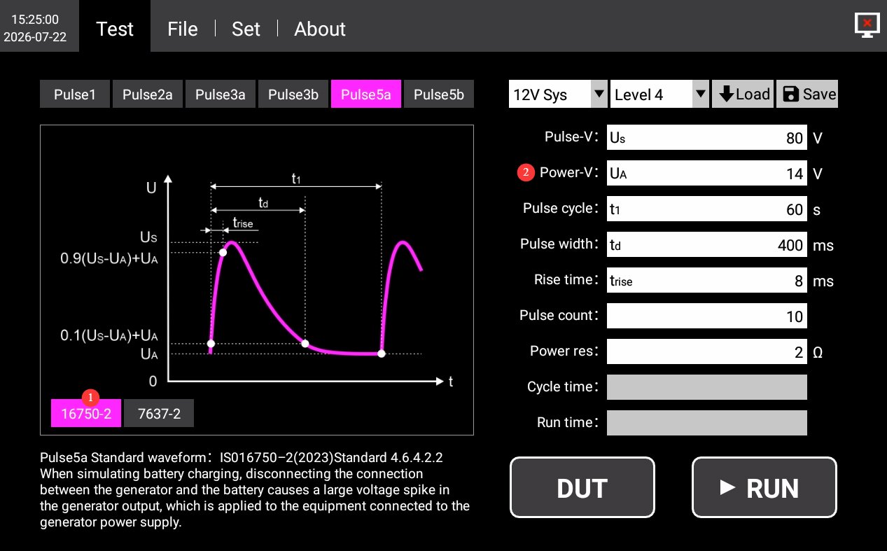
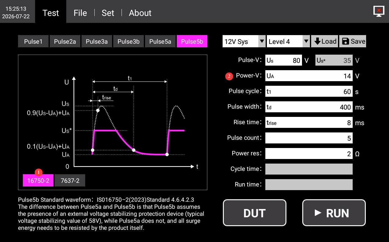
그림 4-7와 4-8을 참조하십시오.
| 번호 | 주의 사항 |
|---|---|
| ① | Select the ISO 16750-2 standard |
| ② | The DUT’s supply voltage must be entered; all other requirements are consistent with ISO 7637-2. |
4.2 데이터베이스 파일 인터페이스
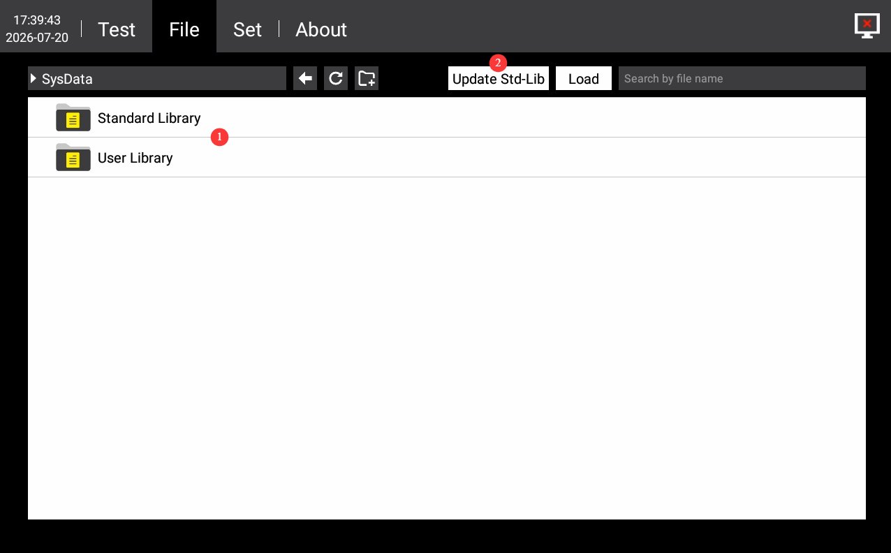
그림 4~9을 참조하십시오.
| 번호 | 주의 사항 |
|---|---|
| ① | 테스트 계획 표준 라이브러리 관리. 저장된 사용자 지정 테스트 매개변수를 관리할 수 있습니다. 장치에 내장된 테스트 매개변수는 수정하거나 삭제하지 마십시오. |
| ② | 다른 표준 시험을 보유하고 있지만 사용자 지정 시험을 제작하고 싶지 않으시다면, 저희에게 연락하여 관련 표준 시험에 대한 정보를 보내주십시오. USB 드라이브를 사용하여 해당 표준 시험으로 데이터베이스 파일을 직접 업데이트하는 방법을 안내해 드리겠습니다. |
4.3 설정 인터페이스
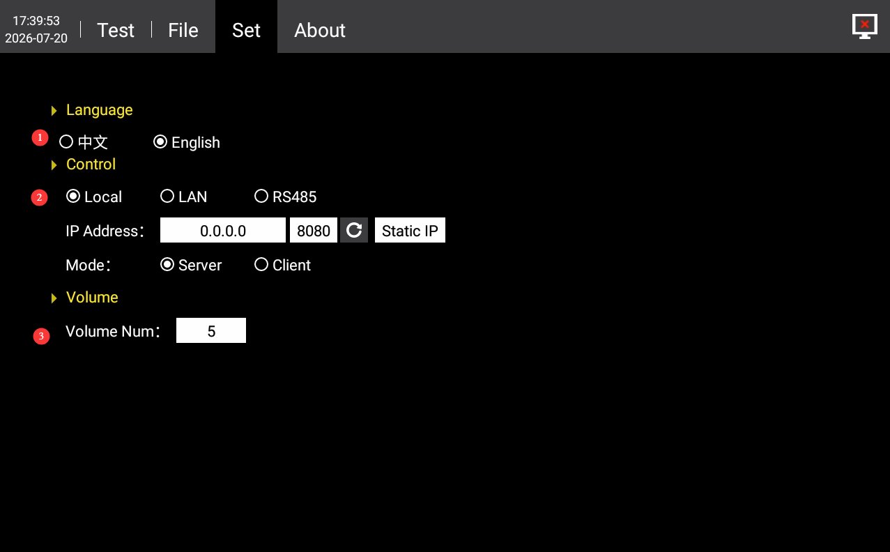
그림 4-10를 참조하세요.
| 번호 | 주의 사항 |
|---|---|
| ① | 중국어와 영어 간 전환 |
| ② | 통신 설정은 기본적으로 "로컬"로 되어 있습니다. 호스트 컴퓨터 소프트웨어를 사용해야 하는 경우 RS485 또는 LAN 포트로 변경할 수 있습니다. 문의해 주십시오. |
| ③ | 볼륨 설정 |
4.4 인터페이스에 대하여
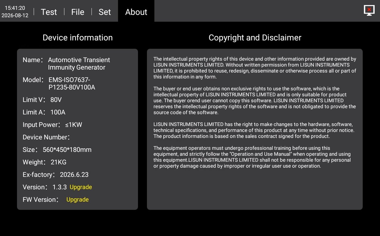
장치 정보, 펌웨어 버전 및 저작권 고지는 그림 4-11를 참조하십시오.
5. Procedures for Automotive Electronic Transient Immunity Testing
5.1 Define the Purpose of the Test
| Waveform | 실험의 목적 |
|---|---|
| 펄스 1 | Verification of the immunity of in-vehicle electronic devices to reverse voltage surges caused by the de-energization of inductive loads |
| 펄스 2a | Verify the device’s immunity to forward voltage spikes caused by stray inductance in the power supply harness |
| 펄스 3a/3b | Verification of the device’s immunity to high-speed, periodic, narrow pulse trains generated by arcing in mechanical switches |
| 펄스 5a/5b | Simulate generator load shedding conditions to verify the equipment’s ability to withstand high-energy voltage spikes |
5.2 일반 운영 절차
5.2.1 배선
Ensure that both the equipment and the DUT are powered off; use a test cable to connect the DUT output port on the equipment to the power input port of the device under test (DUT); Use a cable to connect an external power supply (LIS-APS or other regulated DC power supply) to the DUT input power supply connector on the back of the EMS-ISO7637; if external auxiliary equipment is required, complete the wiring as specified.
5.2.2 매개변수 설정
Set the test parameters as described in Section 4.1.
5.2.3 테스트 실행 단계
Turn on the external power supply and check the DUT output; turn on the DUT power switch on the back of the EMS-ISO7637; switch to the corresponding waveform test interface, tap the DUT button on the touchscreen to verify that the DUT is operating normally; tap the RUN button to start the test; Observe the DUT’s operating status and record any observations; wait for the test to complete—in case of an emergency, press the Stop button to halt the test immediately.
5.3 결과 평가
Grade A: Functionality is normal during and after testing, with no abnormalities; Grade B: Functionality is temporarily degraded or interrupted during testing but automatically recovers after testing; Grade C: Functionality fails during testing and requires manual intervention to recover; Grade D: The equipment is permanently damaged after testing and cannot be restored.
Standard requirements of major automakers: In-vehicle safety components must meet Grade A standards; for in-vehicle electrical systems and infotainment systems, Grade B may be accepted by mutual agreement, while Grade D is uniformly deemed non-compliant.
5.4 시험 종료 후 절차
Ensure that both the equipment and the DUT are powered off; wait until the high-voltage capacitors have fully discharged (it is recommended to wait at least 5 minutes); first disconnect the DUT-side connections, then disconnect the equipment-side connections; disconnect the grounding wire and any connections to auxiliary equipment.
6. 장비의 일상 유지보수 및 관리
6.1 매일 청소
6.1.1 청소 일정 및 절차
사용 후터치스크린 표면을 청소하고 기기 패널의 먼지를 제거하십시오.
매주장비 본체와 통풍구의 필터를 청소하십시오.
월간 회원장비 내부의 먼지를 청소하십시오(전문가가 수행해야 함).
청소 지침
Wipe the exterior with a clean, soft, lint-free cloth; use a specialized screen cleaner for the touchscreen; clean the vents with a soft-bristled brush and a vacuum cleaner if necessary; do not use corrosive solvents such as acetone.
6.2 정기점검
Check the power cord for damage or wear; check that the ground connection is secure; check that the fan is operating normally; check that the buttons and touchscreen are responsive; check the terminals for oxidation or looseness.
6.3 보관 및 취급
6.3.1 장기 보관 요건
Storage Conditions: Temperature: -10°C to +50°C; Humidity: ≤85%. Clean the equipment and apply dust protection before storage. Power on the equipment once every 3 months, running it for at least 30 minutes each time. Avoid stacking or applying heavy pressure to prevent the panel from warping.
6.3.2 취급 시 주의사항
Unplug all external cables before moving the equipment; use the original packaging and ensure it is properly cushioned and protected; keep the equipment upright during transport and avoid severe vibrations; when lifting, grip the bottom and sides of the equipment; do not lift by the panel.
6.4 교정 간격 요구 사항
측정 정확도와 장비의 작동 신뢰성을 보장하기 위해, 자격을 갖춘 제3자 계측 연구소에 정기적으로 보내 교정을 받는 것이 좋습니다. 권장 교정 주기는 12개월입니다. 사용자는 사용 빈도, 환경 조건 및 품질 시스템 요구 사항을 고려하여 구체적인 교정 주기를 결정할 수 있습니다.
7. 문제 해결 및 일반적인 문제 해결 방법
| 결함 증상 | 가능한 원인들 | 순서 |
|---|---|---|
| 기기가 켜지지 않습니다 | 후면의 입력 전원 공급 장치 주 전원 스위치가 켜져 있지 않거나 퓨즈가 끊어졌습니다. | Turn on the input power supply switch located at the power cord socket on the back of the device; check the fuse, and if it has blown, replace it with a fuse of the same specification. |
| 전원을 켠 후 터치스크린 오작동 | 시스템 멈춤, 리본 케이블 느슨함 | If the problem persists after restarting, disconnect the power, remove the device’s casing, and check whether the touchscreen ribbon cable is loose. |
| No pulse output after clicking “RUN” | The DUT did not start up properly | Verify that all connections are secure. Click “DUT” to ensure the DUT is in normal operating condition, then click “RUN” to start the test. |
| 테스트가 도중에 자동으로 중단되었습니다. | 과열 보호 작동, 과전류/과전압 보호 작동, 외부 전원 공급 차단 | 장비의 통풍구가 막혔는지 또는 주변 온도가 너무 높은지 확인하십시오. DUT에 단락이나 과부하가 있는지 확인하십시오. 외부 전원 공급 장치의 전원 출력이 중단되었는지 확인하십시오. |
| USB 드라이브가 인식되지 않음 | USB 드라이브 형식이 호환되지 않거나 저장 용량이 너무 큽니다. | FAT32 형식으로 포맷되고 용량이 32GB 이하인 USB 드라이브를 사용하십시오. 만약 작동하지 않으면 다른 USB 드라이브를 사용해 보세요. |