
 영어
영어 中文简体
中文简体 Русский
 Español
 Português
 Türkçe
 العربية
 Deutsch
 Polski
 Italiano
 Français
 한국어
한국어 ไทย
ไทย Tiếng Việt
 日本語
日本語





























정전기 방전 시뮬레이터
사용자 설명서
적용 할 수있는 LISUN 모델: ESD61000-2P
1. 장비에 대한 기본 이해
1.1 주요 기술 사양
| 파라미터 | 주의 사항 |
| 외관과 스타일 | 휴대용 충전 케이스 |
| Output Voltage | 0.1~20kV ±5% |
| 출력 전압 극성 | 긍정적, 부정적, 긍정적 및 부정적이 번갈아 가며 |
| Install the resistor-capacitor module | 150 pF/330 Ω (replaceable) |
| 방전 전극 | Pointed-tip electrodes (contact discharge), round-tip electrodes (air discharge) |
| Complies with the standards | GB/T 17626.2-2018 (IEC/EN 61000-4-2) |
1.2 장비 구성 검증
1.2.1 포장 풀기
When unpacking the device, handle it gently to avoid scratching the outer casing with sharp tools. After unpacking, first inspect the exterior of the device to ensure there is no visible deformation or dents, and that the buttons are not damaged or loose.
If you notice any damage or deformation to the equipment or accessories, do not turn on the power. Please contact us immediately.
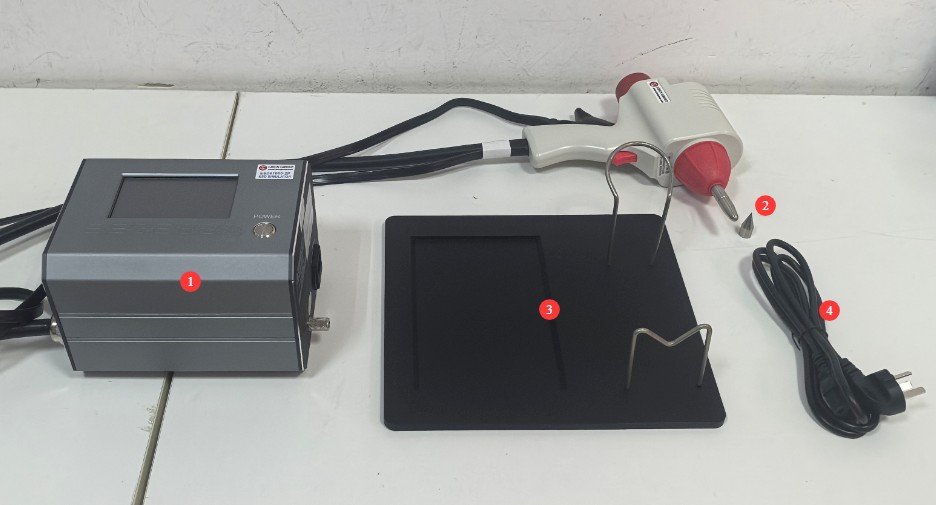
1.2.2 본체 및 부속품
| 번호 | 주의 사항 |
| ① | ESD61000-2P Electrostatic Discharge Simulator Unit (includes electrostatic discharge gun, grounding clamp, and RC module) |
| ② | Pointed-tip electrodes (contact discharge), round-tip electrodes (air discharge) |
| ③ | Electrostatic Discharge Simulator and Electrostatic Gun Holder |
| ④ | 전원 코드 |
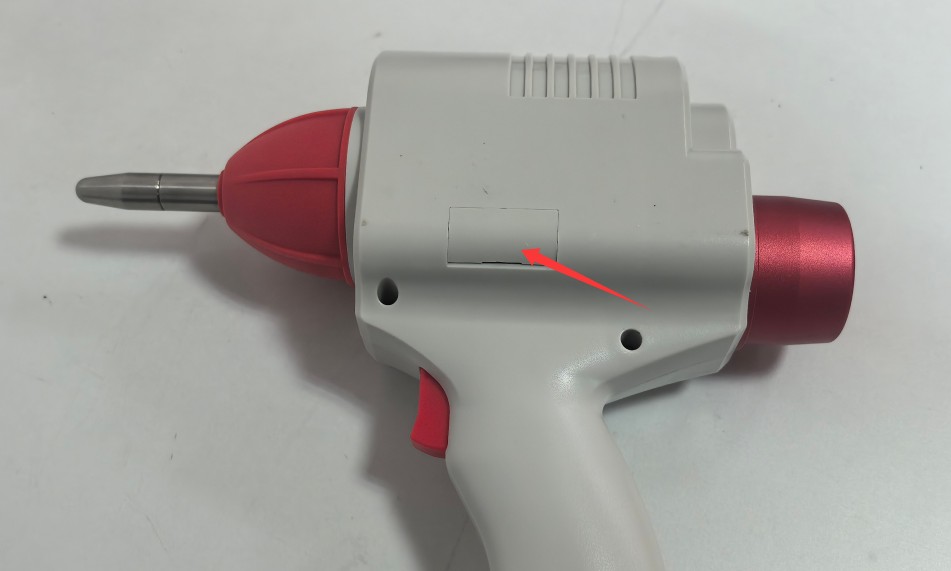
Note: The electrostatic gun comes with one electrode installed at the factory; the other electrode is stored in the electrode compartment, as shown in the figure below:
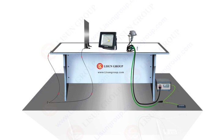
Optional Equipment: ESD-DESK Electrostatic Test Table; the electrostatic test table includes the following accessories:
| 엑세서리 | 주의 사항 |
| 테스트 벤치 | Assembled dimensions: 1600 × 800 × 800 mm |
| Reference Metal Grounding Plate | Length 2800 × Width 1800 × Thickness 1.0 mm |
| 수직 커플링 플레이트 | 500 (L) × 500 (W) × 1.0 mm (Thickness) |
| 수평 커플링 플레이트 | Length 1600 × Width 800 × Thickness 1.0 mm |
| 절연 매트 | Length 1450 × Width 600 × Thickness 0.5 mm |
| 470 kΩ Resistor Cable | 1400 mm long, two pieces |
1.2.3 전자 문서 다운로드
We have already sent the download links for the electronic user manual, warranty card, and other documents via email at the time of shipment. Please download them as soon as possible. If you missed the email, you can contact us to request the download links again.
2. 안전상의 주의
2.1 배치 지침
Place it on a stable work surface; avoid tilting or inverting it, and keep it away from sources of vibration;
The equipment must be placed at least 500 mm away from walls and surrounding structures (such as other test equipment and shelving) to facilitate maintenance; at least 1000 mm of space must be left in front of the equipment to ensure smooth operation, with no obstructions in the surrounding area.
2.2 High-Voltage Safety Standards
2.2.1 보안 검색
전원 공급 장치가 장비와 호환되는지 확인하고, 전원 공급 장치가 제대로 접지되었는지 확인하며, 접지선에 손상이나 느슨함이 없는지 점검하십시오.
Grounding Requirements: The main unit’s protective grounding terminal (PGND) must be connected to a metal reference grounding plate; the grounding resistance must be ≤4Ω; the grounding cable must be securely connected, with no looseness or breaks;
Note that reference ground plates and coupling plates must be connected to the protective ground, and all ground connections must have low impedance to prevent potential differences from occurring during discharge;
2.2.2 운영 절차에 대한 안전 요구 사항
Operators must undergo professional training and be familiar with this manual and the relevant standards. Non-professionals are prohibited from operating or disassembling the equipment. The equipment contains high-voltage circuits; opening the cover may result in a risk of electric shock. Contact the manufacturer’s technical staff for repairs;
After the equipment is powered on, do not touch the discharge gun’s electrode tip, high-voltage connectors, or high-voltage cables;
Operators should have dry hands and not wear any metal jewelry; it is recommended that they wear insulated gloves while working;
During testing, unauthorized personnel are prohibited from remaining within 1 meter of the EUT to prevent accidental electric shock or interference from electrical discharges;
Before replacing the electrodes, you must first ensure that the high-voltage output has been turned off and wait at least 5 minutes to ensure that the internal high-voltage capacitors are completely discharged;
Do not eat or drink during the test to prevent accidents caused by electric shocks;
여러 사람이 참여하는 경우, 역할과 책임을 명확하게 정의하고 오류를 방지하기 위해 테스트 시작 전에 서로 확인해야 합니다.
2.3 기타
본 설명서에 나와 있지 않은 사항에 대해서는 주의를 기울여 진행하시거나 당사에 문의해 주십시오.
3. 장비개요
3.1 Main Unit and Electrostatic Gun
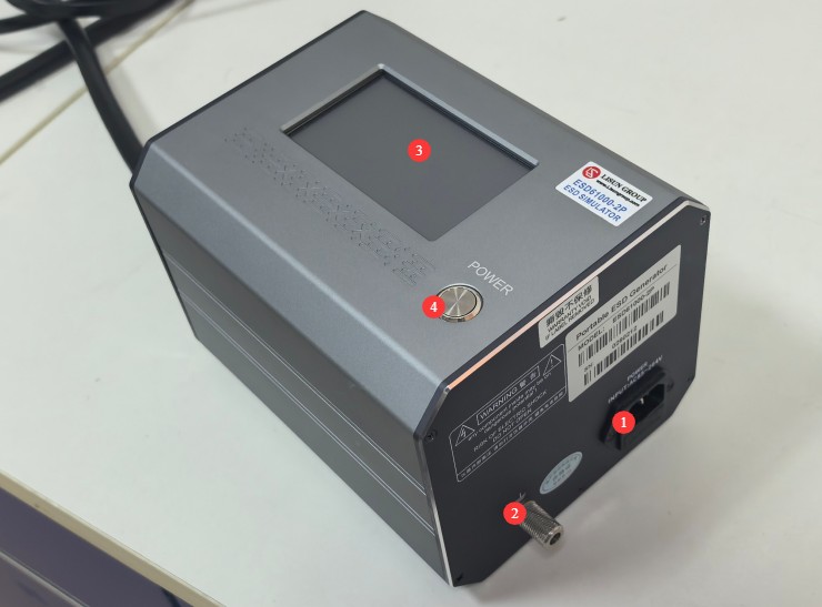
3.1.1 Appearance of the Host Computer
| 번호 | 주의 사항 |
| ① | 기기를 적절한 전원에 연결하기 위한 전원 코드 소켓(퓨즈 포함) |
| ② | PGND Protective Ground Terminal |
| ③ | 터치 스크린 |
| ④ | 전원 스위치 |
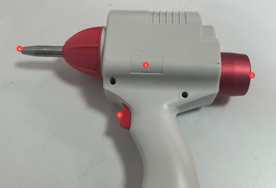
3.1.2 Appearance of the Electrostatic Gun
| 번호 | 주의 사항 |
| ① | Electrode Chamber |
| ② | RC Module Installation Compartment: If you have purchased an additional RC kit, you can unscrew the compartment cover to replace the modules. |
| ③ | 트리거 |
| ④ | 전극 |
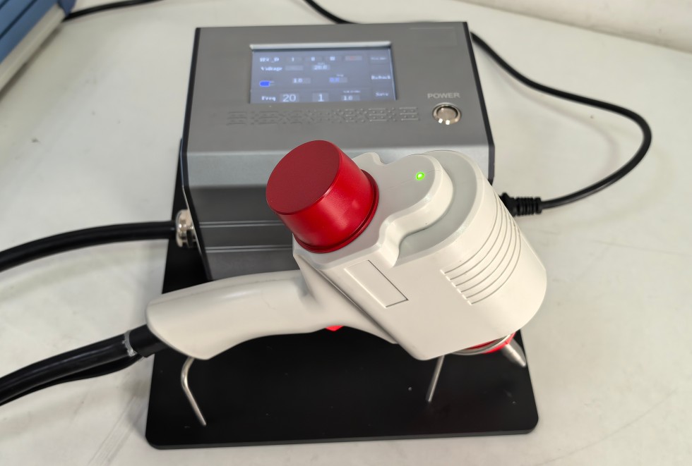
3.1.3 Use of Brackets
4. 터치스크린 프로그램 소개
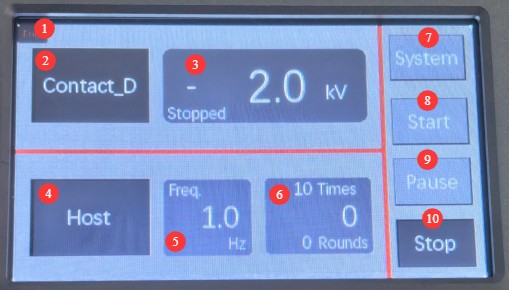
4.1 초기화면
| 번호 | 주의 사항 |
| ① | 중국어와 영어 간 전환 |
| ② | Discharge Mode Selection: Contact Discharge, Air Discharge |
| ③ | Displays the currently set discharge voltage, polarity, and operating status (Stopped: Stopped; Running: Testing; Waiting: Waiting). Tap to access the parameter settings screen. |
| ④ | Trigger mode selection: host-triggered or electrostatic gun trigger-triggered. Note: Either trigger mode can be selected for contact discharge; trigger-triggered mode is the only option for air discharge. |
| ⑤ | Discharge frequency: The discharge frequency can be set for contact discharges, but not for air discharges. |
| ⑥ | Test Count Settings and Display |
| ⑦ | 제품 정보 |
| ⑧ | 스타트 |
| ⑨ | 중지 |
| ⑩ | 중지 |
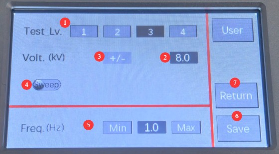
4.2 파라미터 설정 인터페이스
| 번호 | 주의 사항 |
| ① | You can directly select the IEC level to automatically set the discharge voltage |
| ② | You can also set the discharge voltage directly. |
| ③ | Set the discharge polarity: positive, negative, or alternating positive and negative |
| ④ | Step Function: If you need to test automatic voltage switching, you can enable this function to configure the settings. |
| ⑤ | Discharge frequency setting: For example, 1 Hz means a discharge interval of 1 second, and 20 Hz means a discharge interval of 0.05 seconds. Applies only to contact discharge. |
| ⑥ | 찜하기 |
| ⑦ | 뒤 |
5. 시험 전 준비 사항
5.1 Preparation of the Test Environment
Temperature: Adjust the laboratory temperature to 23°C ± 2°C;
Humidity: Use a dehumidifier or humidifier to maintain relative humidity between 45% and 75%; testing in environments where condensation occurs is prohibited;
The facility must be free of strong electromagnetic interference, corrosive gases, flammable or explosive materials, and dust, and must be well-ventilated to prevent sparks from causing hazards;
Atmospheric pressure: Ensure it is within the range of 86–106 kPa. If the laboratory is located at a high altitude, record the atmospheric pressure value for inclusion in the test report.
5.2 Preparing the Test Environment
5.2.1 장비 배치
Standard test environment.
| 번호 | 주의 사항 |
| ① | Reference Metal Grounding Plate |
| ② | 정전기 방전 시뮬레이터 |
| ③ | 정전기 방전 건 |
| ④ | Grounding Clamp for Discharge Gun |
| ⑤ | Wooden Test Table |
| ⑥ | Horizontally Coupled Plate (HCP) |
| ⑦ | 절연 매트 |
| ⑧ | Vertical Coupling Plate (VCP) |
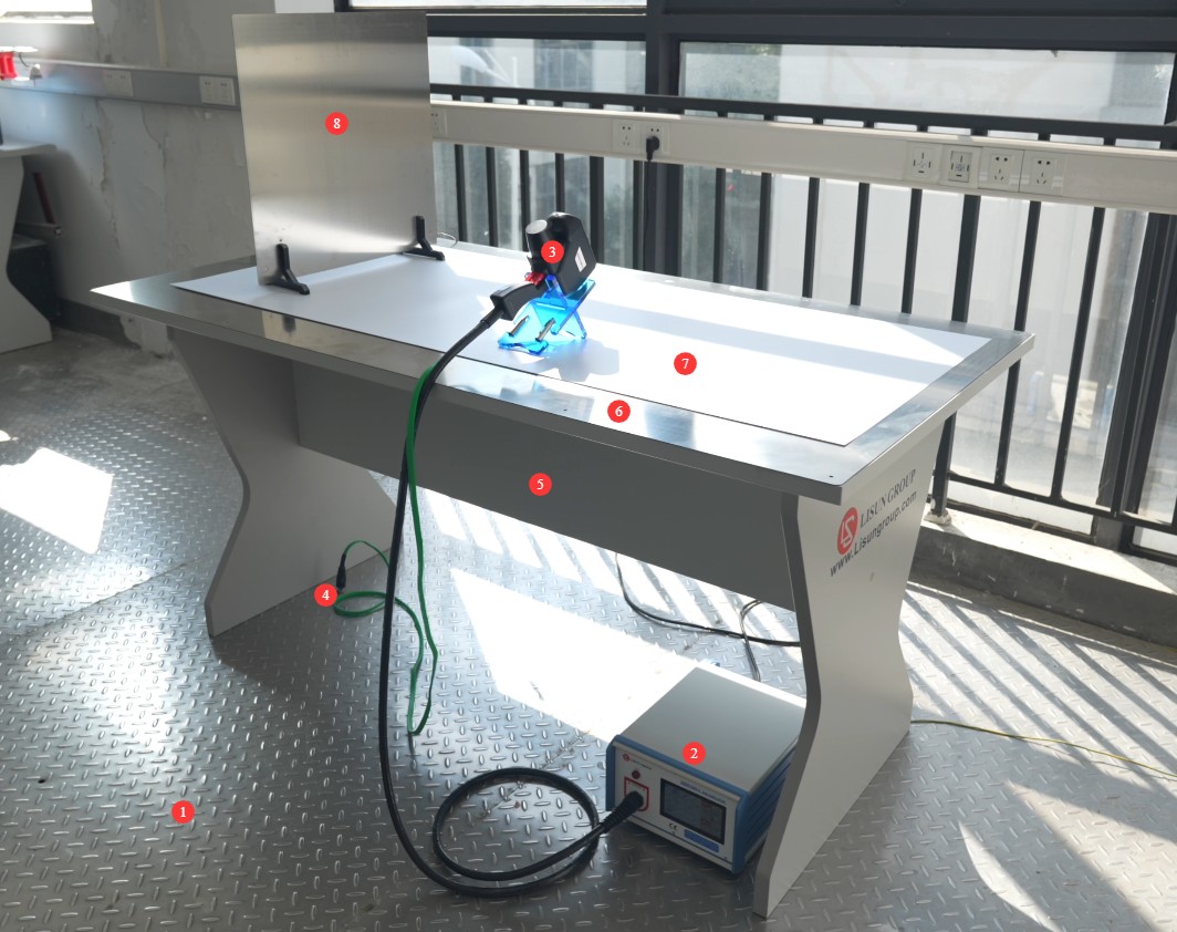
Note: The layout diagram uses the LISUN ESD61000-2 Electrostatic Discharge Simulator as an example.
5.2.2 Grounding System Connections
Main Unit Grounding: Use a wire to securely connect the main unit’s PGND protective ground terminal to the metal reference ground plate, ensuring good contact;
Grounding the Discharge Gun: Connect the discharge gun’s grounding clamp to a metal reference ground plate to prevent induced interference;
Coupling Plate Grounding: The horizontal and vertical coupling plates are connected to the metal reference ground plate via 470 kΩ resistive cables. The resistors must be securely fastened, able to withstand the test voltage, and protected against short circuits.
Grounding via a Reference Metal Grounding Plate: The reference metal grounding plate must be securely connected to the ground to ensure that the grounding resistance of all grounding wires is ≤4 Ω.
5.2.3 Electrode Installation
Replacing the Electrodes: Replace the corresponding electrodes as needed. To remove an electrode, turn it counterclockwise; to install it, turn it clockwise.
5.3 Preparation of the EUT (Equipment Under Test)
5.3.1 Installation and Securing of the EUT
The distance between the EUT and walls, other conductive objects (including operators), shall be at least 1 m;
Benchtop EUT: Place the EUT on a 0.5 mm thick insulating mat positioned above the horizontal coupling plate. The distance between the edge of the EUT and the edge of the coupling plate shall be no less than 0.1 m. If the EUT is too large, two test tables may be joined together, provided that the overlapping section of the coupling plates is no less than 0.3 m;
Floor-mounted EUT: Place the EUT on an insulating mat 0.1 m thick positioned above the metal reference ground plate. The distance between the EUT and the vertical coupling plate shall be 0.1 m, and the dimensions of the vertical coupling plate shall be 0.5 × 0.5 m²;
The EUT must be securely fastened to prevent it from shifting during testing, while maintaining its normal installation configuration (e.g., mounting brackets and wiring arrangements consistent with actual use).
5.3.2 Power Supply and Wiring of the EUT
Connect the power supply in accordance with the EUT’s rated power supply requirements. The power cord should be routed according to the actual usage conditions to prevent it from becoming tangled with the discharge gun cable;
If the EUT requires a signal cable, the signal cable must be kept away from the metal reference ground plane and the coupling plate, and its length must correspond to the actual application; use shielded cable and ground it properly when necessary;
The EUT must be powered on and allowed to warm up in advance to reach normal operating conditions (e.g., by running test software and outputting rated signals) to ensure it is in a stable operating mode during testing.
5.4 Confirmation of Standards and Test Procedures
5.4.1 Determination of Severity Levels
Based on the EUT’s installation environment and usage scenarios, select the severity level in accordance with GB/T 17626.2-2018. Common severity levels are as follows:
| 심각도 수준 | Contact Discharge Voltage (kV) | Air Discharge Voltage (kV) | 적용 가능한 시나리오 |
| 레벨 1 | 2 | Environments with high humidity (≥35%) and no synthetic fabrics | |
| 레벨 2 | 4 | Moderate humidity (10%–35%) and an environment with a small amount of synthetic fabric | |
| 레벨 3 | 6 | 8 | Environments with low humidity (≤50%) and a high proportion of synthetic fabrics (such as offices) |
| 레벨 4 | 8 | 15 | Low humidity (≤10%) and environments with a high concentration of synthetic fabrics (such as drying rooms) |
| 스페셜 그레이드 | 관습 | To be determined through consultation between the manufacturer and the user | |
5.4.2 Test Modes and Parameter Optimization
Discharge Mode: Specify whether to use contact discharge (conductive surface of the EUT), air discharge (insulating surface of the EUT or the receptacle), or indirect discharge (discharge via a coupling plate).
Key Parameters: Discharge voltage, polarity (positive/negative/alternating), number of discharges (typically 10 per point for single polarity), discharge interval (1 second for standard mode, 0.05 seconds for fast scanning).
Test Point Planning: List key test points on the EUT, such as accessible conductive surfaces, insulated surfaces, and sockets, to ensure coverage of all areas that operators may come into contact with (see Appendix A of GB/T 17626.2-2018).
6. Operating Procedures for Electrostatic Discharge Testing (Reference: GB/T 17626.2-2018)
6.1 Touchscreen Operation
After configuring the parameters, click “Start.” The device will begin charging, and the operating status will display “Waiting.” Once charging is complete, the operating status will display “Running,” and you can then proceed with the test.
6.2 Contact Discharge Test (Testing of the EUT’s Conductive Surfaces)
Hold the discharge gun and position the conical electrode tip vertically against the EUT’s conductive test point, ensuring good contact (no gap);
Pull the trigger on the discharge gun (trigger activation) or tap the trigger button on the touchscreen (host activation) to discharge at the set frequency and number of times;
After discharging the specified number of times at each test point, move the discharge gun to the next test point and repeat the test;
During testing, observe the EUT’s operating status in real time (e.g., whether the display is functioning normally, whether any errors are reported, and whether any functions are interrupted), and record any anomalies.
6.3 Air Discharge Test (EUT Insulation Surface/Socket Test)
Hold the discharge gun and position the spherical electrode tip away from the EUT test point (at a distance ≥ the voltage-corresponding distance; 1 kV corresponds to 1 mm; for example, 15 kV requires ≥ 15 mm);
Pull the trigger of the discharge gun (air discharge can only be triggered by the trigger) and hold it down; slowly move the gun toward the test point at an angle perpendicular to the EUT’s surface until a discharge spark occurs;
Immediately after the spark is generated, release the trigger and move the discharge gun backward (to prevent multiple discharges), thereby completing a single air discharge;
Wait at least 1 second before performing the next discharge test, and complete the specified number of discharge cycles (10 cycles per point, 5 cycles each for positive and negative polarity, or as required by the standard);
During testing, observe whether the EUT exhibits any functional abnormalities, and record the location of the discharge points and the nature of the abnormalities.
6.4 Indirect Discharge Test (Coupled-Plate Discharge Test)
6.3.1 매개변수 설정
Set the discharge mode to “Contact” and the discharge frequency to “1 Hz”;
Enter the discharge voltage (based on the severity level) and the number of discharges (10 per side);
6.3.2 Discharge Operations
Place the conical electrode tip of the discharge gun in vertical contact with the surface of the coupling plate (select 3 discharge points evenly spaced on the horizontal coupling plate and 2 discharge points on the vertical coupling plate);
Pull the trigger on the discharge gun (trigger activation) or tap the trigger button on the touchscreen (host activation) to initiate discharge; after completing the set number of discharges, move to the next discharge point;
After completing the discharge point tests on all coupling plates, record whether the EUT is affected by indirect discharge interference.
6.4 Recording Test Results
See Appendix B of GB/T 17626.2-2018:
| 레벨 | 정의 | 결정으로 |
| A | Performs normally within the limits specified by the manufacturer, client, or purchaser | Passed without conditions |
| B | A temporary loss or reduction in function or performance that resolves on its own once the disturbance ceases, without requiring operator intervention | Requires consultation with the manufacturer/user; is generally considered approved. |
| C | A temporary loss or reduction in function or performance that requires operator intervention or a system reset to restore | This must be discussed with the manufacturer/user, depending on the application scenario. |
| D | Loss of functionality or reduced performance resulting from hardware or software damage, or data loss | Unconditional Failure |
7. 테스트 후 절차
7.1 Test Termination Procedure
Once all test points have been completed, click “Stop” to end the test;
Turn off the power to the EUT, and disconnect the EUT from the power supply and signal cables;
Replace the EUT with another one for testing, or turn off the power switch on the main unit of the Electrostatic Discharge Simulator.
7.2 Equipment and Workspace Organization
If the electrode head is dirty, clean it and put it back in place;
Clean the surface of the main unit (wipe with a dry, soft cloth), the discharge gun, the coupling plate, the reference metal grounding plate, and other components.
7.3 장기 보관 요건
When the equipment is not in use for an extended period, it should be stored in a dry, well-ventilated environment (temperature 10°C–40°C, relative humidity ≤60%) to avoid moisture, vibration, and direct sunlight;
Before storage, disconnect all connections, pack components such as the probe head, cables, and coupling plates separately, and place a dust cover over the main unit;
Turn on the device and let it run for 30 minutes each month to prevent internal components from becoming damp and deteriorating.
8. 장비의 일상 유지보수 및 관리
8.1 주간 유지보수
8.1.1 Electrode Head Maintenance
Inspect the contact discharge electrode tip. If the tip is worn, dull, or deformed, replace the electrode promptly to prevent any impact on discharge performance. Check the air discharge electrode tip for scratches or stains, and clean it with a cotton swab dipped in anhydrous ethanol.
8.1.2 Maintenance of Cables and Connectors
Check the outer sheath of the high-voltage cable for damage or cracks. If any damage is found, stop using it immediately and contact the manufacturer to have it replaced;
8.2 월별 유지보수
8.2.1 Resistor-Capacitor Kit Inspection
Unscrew the cap of the discharge gun’s resistor-capacitor kit and check whether the internal 150 pF capacitor and 330 Ω resistor are loose or oxidized; if oxidized, clean the leads or replace the components;
Make sure the cap on the RC kit is tightly screwed on to prevent high-voltage leakage during testing.
8.2.2 Calibration of Discharge Parameters (See GB/T 17626.2-2018, Section 5.4)
Measure the discharge voltage using a calibrated high-voltage meter; the error must be within ±5% (for voltages above 1 kV) or ±10% (for voltages between 0.1 kV and 1 kV);
Measure the discharge current waveform using a 1000 MHz bandwidth oscilloscope to verify that parameters such as the rise time (0.8 ns ± 25%) and peak current meet the standard requirements;
If the parameters are out of tolerance, contact the manufacturer for professional calibration; do not adjust the internal potentiometer yourself.
9. 문제 해결 및 일반적인 문제 해결 방법
9.1 Startup-Related Problems
9.1.1 The Host Won’t Power On
Possible causes: The power cord is not plugged in securely; the outlet has no power; a fuse has blown; or the main unit’s power supply is malfunctioning;
Troubleshooting: Check that the power cord is securely plugged into both the unit and the outlet; try using a different outlet. Check to see if the fuse has blown, and replace it with a fuse of the same rating. If the unit still does not turn on, contact the manufacturer for repair (do not disassemble the unit yourself).
9.1.2 The Touchscreen Is Unresponsive
Possible causes: Stains on the touchscreen surface; the touchscreen has frozen;
Solution: Wipe the touchscreen surface with a dry, soft cloth to remove any smudges; turn off the power, wait 1 minute, then turn it back on. Wait until the self-test is complete before resuming operation.
9.2 Abnormal Discharge Voltage
Possible causes: Loose RC circuit, expired voltage calibration, or aged high-voltage cables;
Solution: Tighten the cap on the RC module and check that the internal capacitors and resistors are securely connected; contact the manufacturer for professional calibration and to update the calibration parameters; check the high-voltage cables for signs of aging or damage.
9.3 Faults Related to Test Results
Fault Symptom: Excessive interference from the EUT (not caused by the EUT itself)
Possible causes: Poor grounding, electromagnetic interference in the test environment, or the coupling plate not connected properly;
Troubleshooting: Re-inspect the grounding system to ensure that the main unit, discharge gun, and reference ground plate are securely grounded; turn off other high-power equipment and RF sources in the test environment to avoid electromagnetic interference; check that the 470 kΩ resistor connection between the coupling plate and the reference ground plate is secure, and replace any damaged resistors.
10. 포장 목록
| 그렇지 않습니다. | 이름 | 수량 |
| ① | ESD61000-2P Electrostatic Discharge Simulator Unit (includes electrostatic discharge gun, grounding clamp, and RC module) | 1 부 |
| ② | Pointed-tip electrode (contact discharge), round-tip electrode (air discharge) | 1 세트 |
| ③ | Electrostatic Discharge Simulator and Electrostatic Gun Holder | 1 |
| ④ | 전원 코드 | 1 조각 |