
 영어
영어 中文简体
中文简体 Русский
 Español
 Português
 Türkçe
 العربية
 Deutsch
 Polski
 Italiano
 Français
 한국어
한국어 ไทย
ไทย Tiếng Việt
 日本語
日本語





























“Go” And “Not Go” Gauge For G13 Lamp Cap
사용자 설명서
적용 할 수있는 LISUN 모델: GNG-B22D,GNG-E27、GNG-G13、GNG-G5
1. 기술 표준
GB 1483-2008
IEC 60061-3 : 2007
2. 사용상의 주의
Handle with care during use; do not subject the gauge to impact to prevent bending or deformation. Testing must be conducted in strict accordance with standard specifications. Do not use the gauge to inspect lamp holders or sockets that are rough or dirty.
3. Name and Model Number
| 이름 | 번호 | 도표 |
| G13 Plug Gauge | 7006-44-4 | 그림 1 |
| G13 General Specifications for Finished Products | 7006-45-4 | 그림 2 |
4. 사용 설명서
(1) G13 Clearance and Interference Specifications (Fig. 1)
Purpose: To verify the dimensions Emin, Emax, Fmin, Gmax, and Hmax of the unassembled G13 double-pin lamp base, including the diameters and displacements of the pins (including the stops).
Instructions for Use: a) When the lamp base pins are fully inserted into the gauge from the O-face, the surface of the lamp base should be in contact with the surface of the gauge.
b) In this position (a), the ends of the two pins shall be coplanar with or protrude from surface X; each pin shall be able to be inserted individually into hole e2 until the pin stop contacts the surface of the gauge, but shall not be able to be inserted into hole e1.
c) The stop on a single pin shall be able to be inserted into hole b from the O-face until the surface of the lamp holder comes into contact with the surface of the gauge.
(2) G13 General Specifications for Finished Products (Figure 2)
Purpose: To inspect the dimensions Emax, Fmin, and Fmax of the G13 double-pin lamp base on the finished lamp, as well as the diameter and displacement of the pins (including the stops).
Instructions for Use: a) When the prongs of the lamp base on the finished lamp are fully inserted into the gauge from the O-face, the surface of the lamp base should be in contact with the surface of the gauge.
b) At this location, the ends of the two pins should be coplanar with or protrude from the X-plane, but should not protrude from the Y-plane.
c) For each order, a single pin shall be able to be inserted into hole e1 from the O-face of the gauge until the surface of the lamp holder comes into contact with the surface of the gauge.
5. 개략도
Note: The following diagrams are for illustrative purposes only.
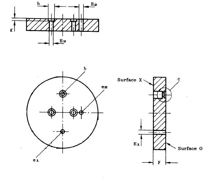
그림 1
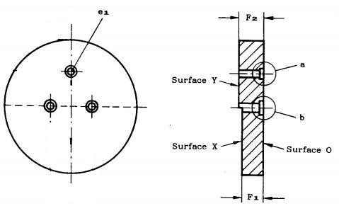
그림 2