
 영어
영어 中文简体
中文简体 Русский
 Español
 Português
 Türkçe
 العربية
 Deutsch
 Polski
 Italiano
 Français
 한국어
한국어 ไทย
ไทย Tiếng Việt
 日本語
日本語





























플러그 핀 테스트용 시험 장치
사용자 설명서
적용 할 수있는 LISUN models: GNGPL-3632
1. 장비에 대한 기본 이해
1.1 적용 범위
The GNGPL-3632 Test Apparatus for Tests on Plug Pins of BS 1363-1 Figure 32 is a specialized testing device designed to evaluate the mechanical strength of British 13A plug pins. By applying a specified static force to the plug pins, it verifies whether they possess sufficient strength to withstand stresses encountered during normal use, thereby ensuring that the plug products meet safety requirements.
1.2 적용 가능한 표준
This equipment is designed and manufactured in strict accordance with the requirements of BS 1363-1:2023, “13A Plugs, Sockets, Adapters, and Connectors—Part 1: Specification for Fused Plugs, Reconnectable and Non-Reconnectable,” specifically clause 13.9.4 and the requirements of Figure 32a and Figure 32b, and fully meets the standard’s strength test requirements for both solid and non-solid pins.
1.3 작동 원리
1.3.1 Principles of Mechanical Testing
The equipment employs a anvil-pressurized testing principle, in which a fixed anvil supports one side of the test pin, while a movable anvil applies pressure perpendicular to the pin’s main axis plane from the other side. By controlling the magnitude of the force, the loading rate, and the number of cycles, the test evaluates the plug’s deformation and structural integrity under specified stress conditions.
1.3.2 Principles of Standards Compliance
The dimensions, shape, clearances, and alignment methods of the equipment’s anvil blocks are strictly processed in accordance with the specifications in BS 1363-1:2023, Figure 32b. Key dimensions—such as the fit clearance between the fixed and movable anvil bases, the fillet radius, and the working surface width—are all controlled within the standard tolerance limits to ensure that test results are consistent with and traceable to the requirements of the standard.
1.4 전자 문서 다운로드
We have already emailed the download links for the electronic user manual, calibration certificate, warranty card, and other documents at the time of shipment. Please download them promptly. If you have not received the email, please contact us to request the download links again.
2. 안전상의 주의
2.1 전기 안전
전원 코드를 연결하기 전에 공급 전압이 AC 220V ±10%이고 주파수가 50Hz 또는 60Hz인지 확인하십시오. 접지 보호 기능이 있는 3구 콘센트를 사용해야 하며, 접지 보호 저항은 4Ω 이하여야 합니다. 접지 보호선을 자르거나 분리하면 감전 위험이 있으므로 절대 하지 마십시오.
2.2 환경 안전
Ambient temperature: 15°C to 35°C; relative humidity: ≤80% RH, no condensation; Installation surface: Level and stable, with minimal vibration; free from strong electromagnetic interference; Do not use in environments with direct sunlight or excessive dust; Do not operate in environments containing flammable, explosive, or corrosive gases; Allow at least 200 mm of clearance around the equipment for operation and heat dissipation.
2.3 작동 안전
Never reach into the anvil’s working area with your hands or any other objects during loading to prevent pinching injuries; when installing plug specimens, ensure they are securely clamped to prevent them from flying out during the test; never strike, grind, or modify the dimensions of the anvil on your own, as this may affect test accuracy; Keep the equipment level when moving or transporting it to avoid severe vibrations and impacts; ensure that no foreign objects are jammed in the drive leadscrew or guide rails, and periodically check for smooth operation.
3. 장비개요
3.1 Standard Diagram
3.1.1 Schematic Diagram of the Plug Test
See Figure 3-1 (taken from BS 1363-1:2023, Figure 32a).
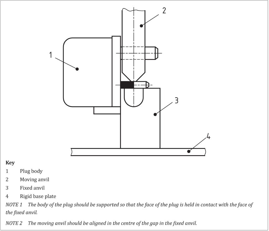
그림 3-1
3.1.2 Schematic Diagram of the Fixed Anvil and Moving Anvil
See Figure 3-2 (taken from BS 1363-1:2023, Figure 32b).
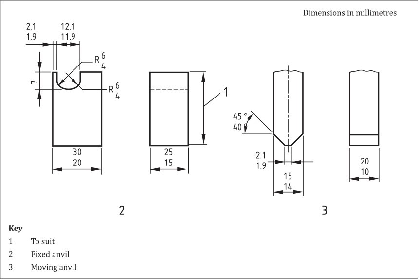
그림 3-2
3.2 Photographs of the Actual Object
3.2.1 Overall Appearance of the Equipment
그림 3-3를 참조하세요.
| 번호 | 주의 사항 |
| ① | 전원 스위치 |
| ② | Current Test Force Display |
| ③ | A spirit level to ensure the equipment is level |
| ④ | 무게 |
| ⑤ | The position of the weight suspension point is adjustable to utilize the principle of leverage to generate different test forces. |
| ⑥ | Lifting screw: When not conducting tests, you can use the screw attached to the screw to lift the lever. |
| ⑦ | Turn the screw by hand to raise or lower the lead screw. |
| ⑧ | Control the up-and-down movement of the lever to ensure that the force is applied vertically downward at the point of application. |
| ⑨ | Point of Application |
| ⑩ | 힘 센서 |
| ⑪ | The plug body is supported to ensure the plug is securely installed |
| ⑫ | Moving Anvil Retaining Screw |
| ⑬ | Moving anvil, corresponding to item 3 in Figure 32b |
| ⑭ | Fixed anvil, corresponding to item 2 in Figure 32b |
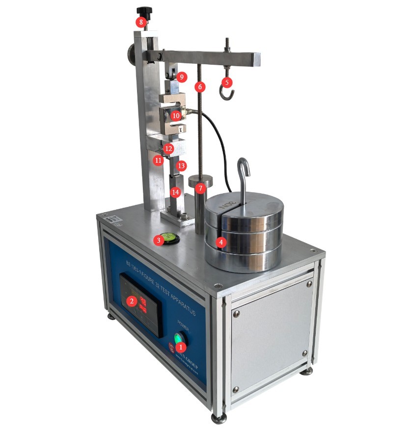
그림 3-3
3.2.2 Detailed Views of the Fixed Anvil and Moving Anvil
그림 3~4을 참조하십시오.
| 번호 | 주의 사항 |
| ① | Moving anvil, corresponding to item 3 in Figure 32b |
| ② | Fixed anvil, corresponding to item 2 in Figure 32b |
| ③ | The plug body is supported to ensure the plug is securely installed |
| ④ | Moving Anvil Retaining Screw |
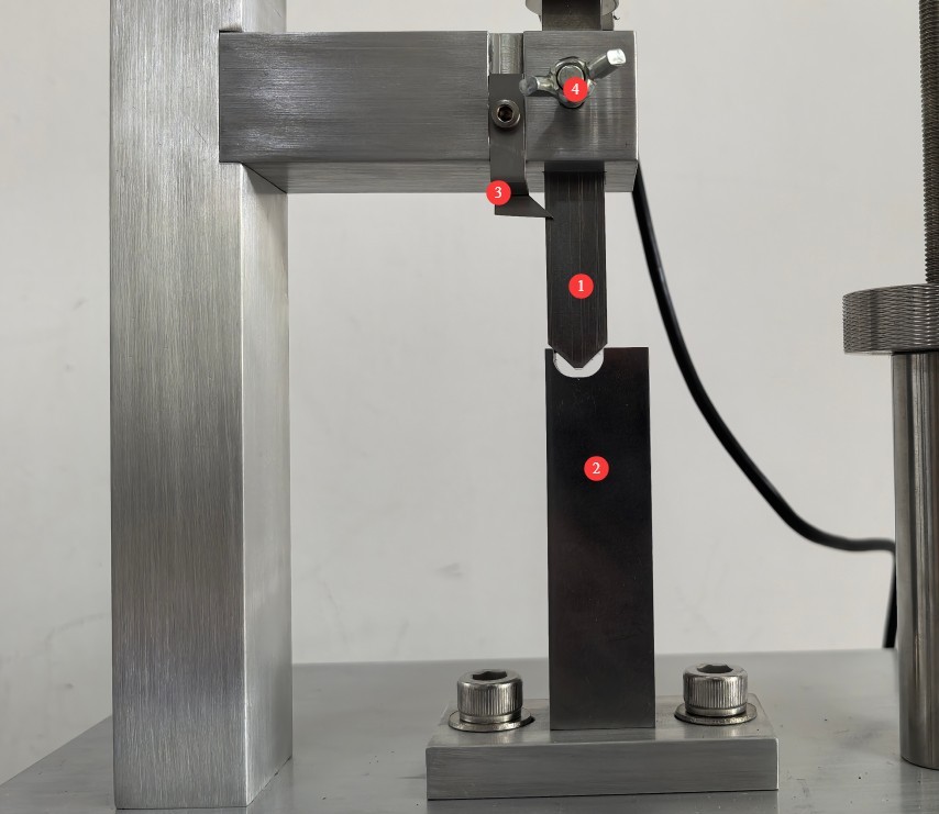
그림 3-4
4. Plug Test Procedure
4.1 Zero Calibration of Force Values
Raise the lead screw to lift the lever, and check whether the current test force reading shows 0. If a force value is displayed, click “CLEAR” on the screen to reset the current force value to zero.
4.2 시편 설치
Install the specimen as shown in Figure 32a.
Place the plug under test horizontally in the slot of the fixed anvil, with the contact surface of the plug lying in the horizontal plane; adjust the plug support so that the end face of the plug is in close contact with the end face of the fixed anvil, and the longitudinal axis of the plug is perpendicular to the slot; confirm that the plug is securely positioned and will not slide or tip over on its own.
4.3 Force Calibration
Loosen the moving anvil retaining screw so that the moving anvil contacts the specimen pin, then tighten the moving anvil retaining screw to prevent force transmission to the specimen pin when the test is not in progress, and then lower the lever. Using different weights and different suspension positions, calibrate the force value displayed on the screen to the desired force value, ensuring that the lever remains level.
4.4 시험 절차
Loosen the moving anvil retaining screw so that the force from the moving anvil is transmitted to the specimen pin. Once the test duration has reached the required time specified in the standard, manually remove the weights, raise the moving anvil, and remove the specimen.
4.5 Evaluation of Results
Visually inspect the plug pins for cracks or obvious deformation; use the gauge specified in Figure 5 to check whether the plug passes the test in accordance with the method described in 13.2.1; if all three pins pass, the test is considered passed.
5. 장비의 일상 유지보수 및 관리
5.1 Daily Maintenance After Shutdown
5.1.1 Device Reset
Use the lead screw to raise the lever, and avoid applying force when the test is not in progress. Secure the moving anvil in a position away from the fixed anvil using the moving anvil set screw to prevent deformation caused by collision or compression.
5.1.2 Equipment Cleaning and Inspection
At the end of each day’s testing, clean dust and sample debris from the equipment surfaces, and keep the fixtures and slide rails clean and free of debris; clean the touchscreen with a dedicated screen-cleaning cloth; and check that the hooks are not loose or deformed.
5.2 Weekly Routine Maintenance
Apply a small amount of neutral lubricating grease to the equipment’s lever and lever pivot, the moving anvil slide rail, and the lead screw to ensure smooth, jamming-free operation.
5.3 Maintenance During Long-Term Storage
After the equipment has been powered off and maintenance has been completed, apply a small amount of rust-preventive oil to the working surface of the anvil base, cover the entire unit with a dust cover, and store it in a dry, well-ventilated warehouse; apply rust-preventive oil to the weights and store them separately; power on the equipment for 30 minutes each month to prevent moisture damage to the components.
5.4 교정 주기 요구사항
측정 정확도와 장비의 작동 신뢰성을 보장하기 위해, 자격을 갖춘 제3자 계측 기관에 정기적으로 보내 교정을 받는 것이 좋습니다. 권장 교정 주기는 12개월입니다. 사용자는 사용 빈도, 환경 조건 및 품질 시스템 요구 사항을 고려하여 구체적인 교정 주기를 결정할 수 있습니다.
6. 문제 해결 및 일반적인 문제 해결 방법
| 결함 증상 | 가능한 원인들 | 순서 |
| Force value drifts from 0 | Force value has not been reset | Refer to Section 4.1; reset the force value to zero and try again. |
| Abnormal Force Value | Moving Anvil Stuttering | Make sure to completely loosen the screws securing the movable anvil and ensure that the movable anvil slide rail is sufficiently lubricated. |