
 영어
영어 中文简体
中文简体 Русский
 Español
 Português
 Türkçe
 العربية
 Deutsch
 Polski
 Italiano
 Français
 한국어
한국어 ไทย
ไทย Tiếng Việt
 日本語
日本語





























절연 변압기
사용자 설명서
적용 할 수있는 LISUN models: ITEU-SP10K、ITEU-SP1KS、ITEU-SP4K,ITEU-SP5K、ITEU-TP10K、ITEU-TP15K、ITEU-TP20K、ITEU-TP60K、ITUS-SP1KS、ITUS-SP2K,ITUS-SP5K,ITUS-TP10K、ITUS-TP5K
1. 장비에 대한 기본 이해
1.1 제품 개요
1.1.1 모델 분류
| LISUN 모델 | 입력 전압 | Output Voltage | 출력 |
|---|---|---|---|
| ITEU-SP1KS | 220 ~ 240V | (220–240 V) × 1.06 | Single-phase / 1 kVA |
| ITEU-SP4K | 220 ~ 240V | 220 ~ 240V | Single-phase / 4 kVA |
| ITEU-SP5K | 220 ~ 240V | 220 ~ 240V | Single-phase/5 kVA |
| ITEU-SP10K | 220 ~ 240V | 220 ~ 240V | Single-phase / 10 kVA |
| ITUS-SP1KS | 110 ~ 120V | (110–120 V) × 1.06 | Single-phase / 1 kVA |
| ITUS-SP2K | 110 ~ 120V | 110 ~ 120V | Single-phase / 2 kVA |
Selection Guidelines: For resistive loads, select a rated capacity that is 1.5 times the actual power; for inductive and inrush loads (such as EMC test equipment and motors), select a rated capacity that is 2 times the actual power.
1.1.2 제품 응용
Electronics and Electrical Laboratory: Provides isolated power supply for EMC tests (such as lightning surge and ringing wave tests) and safety compliance testing equipment.
Precision Instruments and Industrial Control: Provides interference-resistant, isolated power supplies for precision measurement equipment and industrial control devices.
Medical and Machine Tool Equipment: Reduce the risk of electrical leakage and enhance equipment operational safety.
Live-line commissioning and maintenance scenarios: Provides isolation protection for live-line work and reduces the risk of electric shock.
1.2 Unboxing and Checking the Contents
1.2.1 Unpacking and Visual Inspection
When unpacking the device, handle it gently to avoid scratching the casing with sharp tools. After unpacking, first inspect the exterior of the device to ensure there is no visible deformation or dents, and that the buttons are not damaged or loose. If you notice any abnormalities with the device or its accessories, please contact us immediately.
1.2.2 Main Unit and Accessories
| 번호 | 주의 사항 |
|---|---|
| ① | ITEU-SP Series Hosts |
| ② | 입력 케이블 |
| ③ | 출력 케이블 |
1.2.3 Downloading Electronic Documents
Download links for the digital user manual, warranty card, calibration certificate, and other documents have been sent via email. Please download them as soon as possible. If you missed the email, please feel free to contact us to request the download links again.
2. 안전상의 주의
2.1 General Security Guidelines
2.1.1 Personal Safety Protection
All wiring, maintenance, and troubleshooting operations must be performed with the power completely disconnected. After disconnecting the power, wait at least 5 minutes to ensure that any residual voltage has been fully discharged before proceeding.
When operating the equipment, you must wear insulated gloves and use insulated tools; under no circumstances should you touch any live parts of the equipment with wet hands.
While the equipment is in operation, do not remove the panel, plug or unplug the output connector, or touch the terminals to avoid the risk of electric shock.
The equipment must be reliably connected to the protective grounding (PE); it is prohibited to energize and operate the equipment without a grounding connection.
2.1.2 Equipment Safety Requirements
The equipment must be placed in a dry, well-ventilated environment free of corrosive gases and flammable or explosive materials. Do not use the equipment in damp, excessively dusty, or direct sunlight environments.
Overloading is strictly prohibited; the continuous operating load must not exceed 80% of the rated capacity, and direct short-circuiting of the output terminals is prohibited.
Leave at least 10 cm of space around the equipment for heat dissipation. Do not cover the equipment or pile items on top of it, as this may interfere with ventilation and heat dissipation.
Non-professionals are strictly prohibited from disassembling the internal components of the equipment; unauthorized modifications to the circuitry or replacement of components are prohibited.
2.2 Safety Standards for Installation and Wiring
2.2.1 Safety Requirements Before Wiring
Ensure that the input mains voltage matches Input Voltage; do not connect the device if the voltage exceeds the specified range.
Before connecting the wires, you must turn off the upstream power circuit breaker.
Cable selection should follow the national standards for copper-core current-carrying capacity. For the 4KVA model, the recommended input cable cross-sectional area is ≥2.5mm²; for the 10KVA model, it is ≥6mm². Do not use cables with small cross-sectional areas for high-power equipment to prevent cable overheating and fire.
Verify that the upstream power supply circuit is equipped with overload and short-circuit protection.
2.2.2 Safety Requirements for the Wiring Process
The wiring sequence is as follows: “Connect the protective ground first, then the neutral wire, and finally the live wire.” The sequence for disconnecting the wires is the reverse.
Cable ends must be stripped according to specifications, crimped securely, and free of exposed copper wires to prevent short circuits or overheating caused by poor contact.
Never connect the input and output circuits in reverse; do not connect the input power supply to the output terminals to prevent damage to the equipment and downstream loads.
After completing the wiring, you must verify the wire sequence and tightness; only after confirming that everything is correct should you close the switch to energize the circuit.
2.3 Safety Prohibitions During Operation and Maintenance
2.3.1 Safety Taboos During Operation
Never plug or unplug the output plug from the industrial outlet while the device is running; plugging or unplugging under load may cause arc flash burns or damage the contacts.
Do not switch the “N-wire ground selection switch” while the system is running; turn off the power first and set the switch to the appropriate position based on the application.
If any abnormalities occur during equipment operation—such as smoke, unusual noises, or a burning smell—the power supply must be immediately shut off, and the equipment must not be left powered on.
2.3.2 Safety Requirements for Maintenance and Repair
All maintenance and repair work must be performed with the power off, and it must be confirmed that there is no residual voltage in the equipment.
Insulation resistance tests must be performed by a licensed electrician, and the windings must be thoroughly discharged after the test is complete.
If the device experiences an internal malfunction, do not attempt to disassemble or repair it yourself; contact the manufacturer or an authorized service provider for assistance.
3. 장비 개요 및 배선
3.1 Description of Equipment Structure
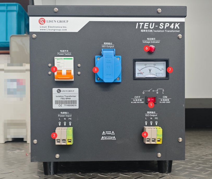
받아 ITEU-SP4K as an example; see Figure 3-1.
| 번호 | 주의 사항 |
|---|---|
| ① | 전원 스위치 |
| ② | 전원 입력 단자 |
| ③ | Isolated-Output Industrial Outlet |
| ④ | The isolated output terminal block functions identically to the isolated output industrial connector; you can connect to either one. |
| ⑤ | N-wire grounding selector switch. OFF position: Output N-wire is floating (isolated from ground); ON position: Output N-wire is connected to protective ground |
| ⑥ | Output Voltage Indicator Light |
| ⑦ | Analog Output Voltmeter |
3.2 배선 절차
3.2.1 Power Input Wiring
Verify that the main power supply has been turned off and that the equipment’s power switch is in the OFF (down) position.
Connect the wires in the order indicated by the terminal labels: PE 터미널 (protective ground), tighten the securing screw; N 단자 (neutral), tighten the securing screw; L 터미널 (live wire), tighten the securing screw.
Gently pull on the cable to ensure the connection is secure and that the exposed copper wires are fully seated in the terminal with no protruding ends.
3.2.2 Wiring the Isolated Output Terminals
The device offers two output options; choose one of the two:
Industrial Outlet Output (For Quick Connection and Disconnection): Connect the load cable to the matching industrial plug according to the L/N/PE wire sequence, then insert the plug into the blue isolated output outlet on the panel.
Hard-wired terminal output (for fixed installations): Following the input wiring method, connect the load cables to the corresponding L, N, and PE terminals on the output side, and tighten them securely.
Note: The PE terminal on the output side is a protective ground and is electrically connected to the equipment chassis and the input PE; it is not considered part of the electrical isolation circuit.
3.2.3 Installation of N-Line Grounding Switches
With the power off, set the switch position according to the application:
OFF Position (N-Line Floating to Ground): The output N-line has no electrical connection to the protective ground, providing optimal isolation. This is suitable for safety compliance testing, surge testing, and live-line maintenance, and can significantly reduce the risk of electric shock.
ON Position (N Wire Grounded): The output N wire is connected to the protective ground. This is suitable for powering ordinary precision equipment and applications with general interference immunity requirements.
Note 1: The factory default setting is the OFF position (N wire floating to ground); switching positions while the power is on is strictly prohibited.
Note 2: The “ON” setting must not be used during EMC lightning surge testing, with medical equipment, or in live-line maintenance scenarios; otherwise, the isolation function will fail, significantly increasing the risk of electric shock and testing errors.
4. Equipment Operation and Use
4.1 Standard Startup Procedure
4.1.1 No-Load Power-On Test
Close the circuit breaker in the upstream power supply circuit and verify that the input mains power is normal.
Slide the power switch on the device panel upward to the ON position.
Check the operating status: If the red power indicator light is on, the unit is properly powered; if the voltmeter needle reads between 220 and 240 V, the output voltage is normal; ensure there are no unusual noises, odors, or smoke coming from the unit. Allow the unit to run under no-load conditions for 1 minute, and only connect the load once the unit has stabilized.
4.1.2 Load Operation
After confirming that the unit operates normally under no-load conditions, if multiple loads are connected, turn on the low-power devices first, followed by the high-power devices.
After applying the load, observe the voltmeter; voltage fluctuations within ±10% of the rated voltage are considered normal.
Monitor the operating status at all times. If any abnormalities occur—such as excessive voltage sags or unusual noises—shut down the system immediately to investigate.
4.2 Operational Status Monitoring
4.2.1 Checking the Voltage Indicator
During normal operation, the voltmeter needle should remain stable within the 220–240 V range.
If the voltage exceeds the specified range, first check whether the input mains power is normal, and then check whether the load is overloaded.
4.2.2 Key Points for Operational Status Inspections
Equipment Housing Temperature: During normal operation, the temperature rise of the housing should not exceed 60 K (the maximum housing temperature should not exceed 85°C in a 25°C ambient environment); it is normal for the housing to feel warm to the touch. If it feels hot to the touch, check for overloading or heat dissipation issues.
Operating Noise: Under normal conditions, the sound should be a steady, low-frequency electromagnetic hum; if a high-pitched noise or grinding sound occurs, shut down the machine immediately for inspection.
Terminal blocks: No overheating, discoloration, or burning odor; if an abnormal temperature rise occurs, disconnect the power and tighten the terminals.
4.3 종료 절차
4.3.1 Standard Shutdown Procedure
Shut down all backend load-balancing devices one by one, and wait until the load has completely stopped.
Slide the device’s power switch down to the OFF position; the red indicator light will turn off.
If the equipment will be out of service for an extended period, disconnect the circuit breaker in the upstream power supply circuit.
4.3.2 Emergency Shutdown Scenarios and Procedures
Perform an emergency shutdown if any of the following conditions occur: the device emits smoke, gives off a burning odor, or catches fire; there are loud, unusual noises or crackling sounds coming from inside the device; there is a risk of electric shock to personnel; or an emergency situation such as a short circuit at the output terminal or water ingress occurs.
순서: Immediately turn off the device’s power switch and simultaneously turn off the main power switch at the upstream power source; if a fire breaks out, use a dry powder fire extinguisher to put it out; do not use water to extinguish the fire.
5. 정기 유지보수 및 관리
5.1 정기적 인 유지 보수
Maintenance and Cleaning During Power-Off: Wipe the equipment housing and control panel with a dry, soft cloth to remove dust and stains; use a soft-bristled brush to clean dust accumulated in terminal gaps and heat dissipation vents; do not rinse with liquid; After cleaning, check all terminal screws for looseness and retighten them; if the operating environment occasionally has floating dust, it is necessary to disassemble the equipment housing and clean the accumulated dust inside.
5.2 Long-Term Storage and Maintenance Requirements
5.2.1 Storage Environment Requirements
Storage temperature: -10°C to +55°C; relative humidity ≤ 85%; no condensation.
Storage Location: A dry, well-ventilated indoor area free of corrosive gases and dust.
Do not stack heavy objects on top of each other, and do not store them together with flammable, explosive, or corrosive substances.
5.2.2 Pre-Storage Preparation and Periodic Inspections
Clean the surface of the equipment before storage, pack it to protect it from dust and moisture, and ensure the terminals are properly protected.
Open the box and inspect it once every 3 months to check for moisture or rust; if the environment is humid, place a desiccant inside.
6. 문제 해결 및 일반적인 문제 해결 방법
6.1 No output when powered on; indicator light does not illuminate
| 가능한 원인들 | Troubleshooting and Resolution Methods |
|---|---|
| No power from the upstream source / Circuit breaker tripped | Use a multimeter to measure the voltage at the input terminals and verify that the mains power is normal; close the upstream circuit breaker. |
| Equipment Power Switch Tripped / Damaged | Check whether the power circuit breaker is in the OFF position, then attempt to close it; if it trips immediately after closing, check for a short circuit in the output. |
| Loose or broken input wiring | After turning off the power, tighten the input terminals and check the cables for breaks or poor connections. |
| The built-in protective element has blown. | After a power outage, contact customer service to have the unit inspected and replaced; do not replace any components that do not meet specifications on your own. |
6.2 Abnormal Output Voltage (Too High / Too Low / Unstable)
| 가능한 원인들 | Troubleshooting and Resolution Methods |
|---|---|
| Abnormal Mains Voltage Input | Use a multimeter to measure Input Voltage and verify that it is within the 220–240 V range; if it is outside this range, troubleshoot the upstream power supply. |
| Load Overload | Calculate the total power load of the backend and verify that it does not exceed 80% of the rated capacity; then reduce part of the load and monitor the results. |
| Poor contact in the output wiring | After turning off the power, tighten the output terminals and check the cables and plugs for oxidation or looseness. |
| Voltmeter Indication Error | Use a high-precision multimeter to measure the actual voltage at the output terminal. If the measured voltage is normal and only the meter’s pointer is off, the device’s power supply function remains unaffected; however, you should contact customer service as soon as possible to have the voltmeter calibrated or replaced to avoid misjudgments during operation. |
6.3 Unusual Noises or Odors During Equipment Operation
| 가능한 원인들 | Troubleshooting and Resolution Methods |
|---|---|
| Load Overload | Reduce the load power and see if the unusual noise stops. |
| The equipment is not positioned securely | Adjust the position of the equipment to ensure that all four corners are in stable contact and to eliminate resonance. |
| Loose internal core | After the power is turned off, contact customer service to have the issue resolved; do not attempt to disassemble the unit yourself. |
| Aged internal insulation / Localized short circuit | If you notice a burning smell or see smoke, immediately unplug the device and stop using it, then contact customer service to have it returned to the factory for repair. |
6.4 Frequent Tripping of the Power Circuit Breaker
| 가능한 원인들 | Troubleshooting and Resolution Methods |
|---|---|
| 출력 단락 | After turning off the power, use a multimeter to measure the resistance between the output terminals L-N, L-PE, and N-PE to identify and eliminate any short circuits. |
| Excessive load power | Calculate the total load power to ensure it does not exceed the rated capacity, and remove any overloaded loads. |
| Excessive load startup surge | Start the loads one at a time to avoid starting high-power equipment simultaneously. |
| Aging and Damaged Circuit Breakers | If the circuit breaker continues to trip after ruling out load-related issues, contact customer service to have the circuit breaker replaced. |