
 영어
영어 中文简体
中文简体 Русский
 Español
 Português
 Türkçe
 العربية
 Deutsch
 Polski
 Italiano
 Français
 한국어
한국어 ไทย
ไทย Tiếng Việt
 日本語
日本語





























고온·고압 방수 시험 챔버
사용자 설명서
적용 할 수있는 LISUN models: JL-4K6K9K1L-R400、JL-56K9K1L,JL-56KCA-1000L,JL-6K9K1L,JL-9K1L
1. Basic Understanding of Test Chambers
1.1 제품 개요
1.1.1 적용 가능한 표준
GB/T 4208-2017 “Degrees of Protection Provided by Enclosures (IP Code),” Clause 14.2.9;
IEC 60529:2013, “Degrees of Protection Provided by Enclosures (IP Code),” Clause 14.2.9;
GB/T 7000.1-2023 “Luminaires—Part 1: General Requirements and Tests,” Clause 10.2.5;
GB/T 30038-2013 “Road Vehicles—Degrees of Protection Provided by Enclosures (IP Code),” Clause 5.3.5;
ISO 20653:2023, “Road vehicles—Degrees of protection (IP-code) for electrical and electronic equipment,” Clause 5.3.5;
DIN 40050-9:2009, “Road Vehicles—Protection of Electrical Equipment against Foreign Objects, Water, and Access,” Clause 6.3;
VW 80000:2018, “Requirements for Electrical and Electronic Components in Motor Vehicles—Environmental Conditions and Test Requirements,” Section 5.2.3.
1.1.2 응용 시나리오
Automotive Parts: In-vehicle sensors, connectors, automotive lighting, power battery packs, engine control systems;
Electronics and Electrical Equipment: Outdoor security equipment, industrial control instruments, power tools;
Lighting Equipment: Outdoor LED fixtures, tunnel lights, mining lights;
New Energy Products: Outdoor charging stations, energy storage systems, and photovoltaic inverters;
Construction Machinery: Electrical components and seals for equipment such as excavators and loaders;
Rail Transit: On-board electrical equipment and signaling systems;
Third-Party Testing Organizations: IPX9K compliance certification testing for various types of products.
1.2 주요 매개 변수
| 파라미터 | 주의 사항 |
|---|---|
| 내부 챔버 치수 | 1000 1000 × × 1000 MM |
| Dimensions and Weight of the Test Object | Maximum diameter of 350 mm and 50 kg (meets the testing requirements for small and medium-sized enclosures and some large enclosures as specified in Clause 14.2.9 of IEC 60529:2013) |
| Water temperature inside the tank | Up to 80±5°C (adjustable): Equipped with temperature overload and water overflow protection devices |
| Number and Size of Nozzles | Includes 4 nozzles; dimensions strictly comply with the requirements of IEC 60529:2013, Figures 7, 8, and 9 |
| 스프레이 각도 | 0 °, 30 °, 60 °, 90 ° |
| 스프레이 거리 | 125±25 mm (Multifunctional nozzle adjustment device: When adjusting the nozzle distance, this ensures that all four nozzles remain on the same arc relative to the test object, while maintaining a constant angle) |
| 스프레이 유량 | 14–16 L/min (high-temperature-resistant electronic flow meter) |
| 스프레이 압력 | 8~10MPa |
| 테스트 턴테이블 직경 | One each of φ400 and φ200 mm |
| Testing the Turntable Speed | Turntable speed: 1–5 r/min (speed controlled by a motor-driven gear, with support for variable-frequency adjustment) |
| 시험 시간 | 30초 또는 3분 (설정 및 조정 가능) |
| 기타 | Includes a force calibration system (compliant with IEC 60529:2013, Figures 10 and 11); both the inner and outer chambers are made of high-quality stainless steel; features a large glass viewing window |
1.3 액세서리 개봉, 검사 및 확인
1.3.1 포장 해제 및 육안 검사
기기를 개봉할 때는 날카로운 도구로 외부 케이스에 흠집이 나지 않도록 조심스럽게 다루십시오. 개봉 후에는 먼저 기기 외부를 검사하여 눈에 띄는 변형이나 찌그러짐이 없는지, 버튼이 손상되었거나 헐거워지지 않았는지 확인하십시오. 기기 또는 부속품에 이상이 발견되면, 켜지 마세요즉시 저희에게 연락주세요.
1.3.2 전자 문서 다운로드
디지털 사용 설명서, 보증서, 교정 인증서 및 기타 문서 링크는 이메일로 발송되었습니다. 이메일을 받지 못하신 경우, 저희에게 연락하시면 링크를 다시 보내드리겠습니다.
2. 안전상의 주의
2.1 전기 안전 표준
2.1.1 Power Supply and Grounding Requirements
Use the 380V three-phase power supply specified on the equipment nameplate; under no circumstances use a power supply with a voltage or frequency other than the rated values. The equipment must be reliably grounded, with a grounding resistance of ≤4Ω. It is recommended to install a properly rated ground-fault circuit interrupter (GFCI) in the equipment’s power supply circuit to enhance electrical safety.
2.1.2 Safety Precautions for Electrical Operations
Never touch the power cord, plug, or electrical components of the equipment with wet hands; do not pull or pinch the power cord to prevent damage to the insulation; unauthorized personnel must not open the equipment’s electrical enclosure door, and must not alter electrical circuits or parameters without authorization; If the equipment is to be out of service for an extended period, the main power supply and power cord must be disconnected to prevent safety hazards associated with standby mode.
2.2 Safety in High-Temperature and High-Pressure Operations
During the water tank heating process and after the test is complete, do not touch the interior of the water tank, the metal walls of the inner tank, or the nozzle components to prevent burns; After the test is complete, do not open the chamber door fully all at once. First, leave the door slightly ajar (5–10 cm), and wait until the high-temperature steam has dissipated before opening it fully. When removing or placing samples in a high-temperature environment, you must wear heat-resistant gloves; do not touch the samples or high-temperature components inside the chamber with bare hands.
2.3 Prohibitions on Routine Operations and Emergency Response Procedures
2.3.1 Prohibited Operations During Operation
Do not arbitrarily modify operating parameters, and do not frequently start and stop the equipment. Do not place foreign objects inside the enclosure; keep the chamber dry and clean to prevent debris from clogging the water lines. Samples must be securely fastened to the turntable to prevent them from falling off and striking the equipment during rotation. Operators must not leave their posts while the equipment is running and must monitor its operating status at all times.
2.3.2 비상 대응 절차
If the equipment emits unusual noises, leaks water, experiences an electrical leak, or emits smoke during operation, immediately press the emergency stop button on the control panel to stop all equipment operations immediately; if necessary, cut off the equipment’s main power supply directly; after the fault has been resolved, turn the emergency stop button clockwise to reset it.
2.4 기타
본 설명서에 나와 있지 않은 사항에 대해서는 주의를 기울여 진행하시거나 당사에 문의해 주십시오.
3. Introduction to Basic and Connections
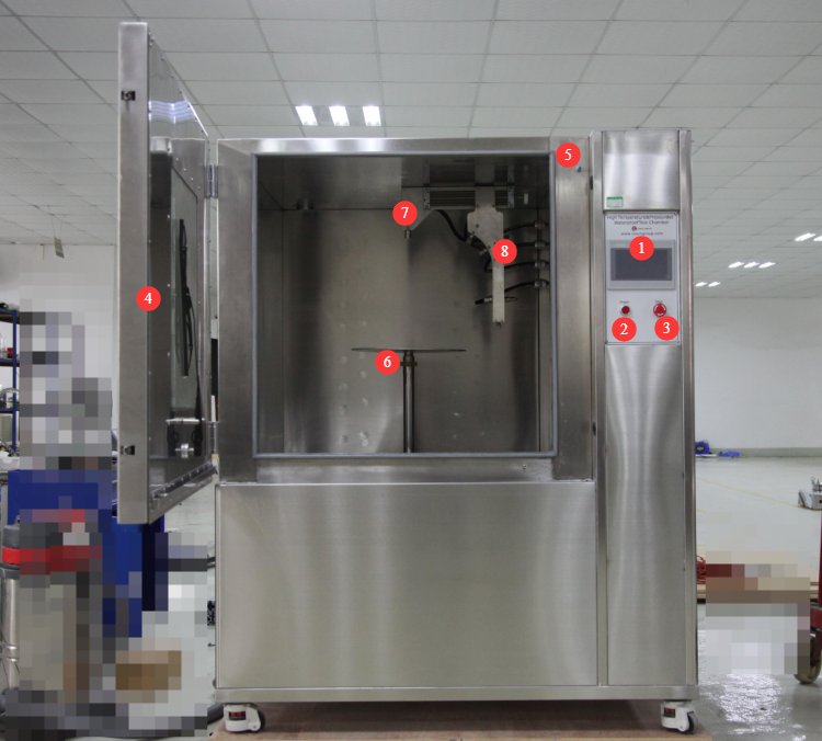
3.1 Front of Basic
그림 3-1를 참조하세요.
| 번호 | 주의 사항 |
|---|---|
| ① | 터치 스크린 |
| ② | 전원 스위치 |
| ③ | 비상 정지 버튼 |
| ④ | Basic Door |
| ⑤ | Safety sensor button: The test cannot be initiated while the door is open. |
| ⑥ | Sample turntable; turntable size is interchangeable, and turntable height is adjustable |
| ⑦ | 90° Nozzle |
| ⑧ | 0°, 30°, and 60° nozzles, adjustable left and right as well as up and down |
3.2 Rear of the Basic
그림 3-2를 참조하세요.
| 번호 | 주의 사항 |
|---|---|
| ① | Connect the Basic chamber’s power cord to an appropriate power source, as indicated on the product nameplate. |
| ② | Sample Power Terminals: If the sample requires power during the test, connect it to an appropriate power source according to the sample specifications. |
| ③ | Water inlet: Must be connected to a purified water supply system that provides a certain level of water pressure. |
| ④ | Drain outlet: To clean the tank or to drain water from the tank, open the drain valve to drain the water. |
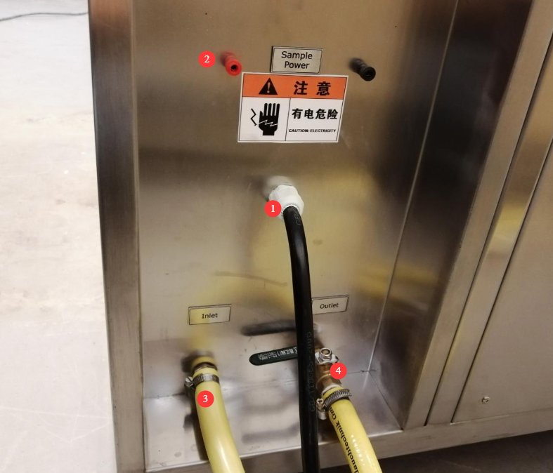
Note: Before using Basic for the first time, thoroughly clean the interior of both the test chamber and the water tank.
4. 터치스크린 프로그램 소개
4.1 시간을 아껴주는 인터페이스
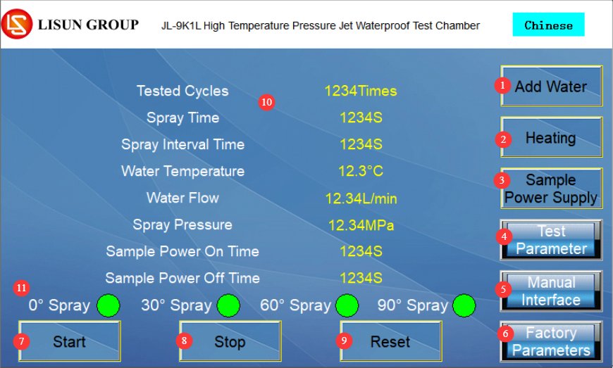
After Basic is turned on, the touchscreen program automatically enters the operating interface, as shown in Figure 4-1.
| 번호 | 주의 사항 |
|---|---|
| ① | “Add Water” button: Press to refill the water tank; refilling stops automatically when the tank is full. |
| ② | Heating button: Press to heat the water tank; once the target temperature is reached, the unit automatically switches to keep-warm mode. |
| ③ | Sample Power Button: If the sample requires power during the test, press this button. |
| ④ | Test Parameter Settings |
| ⑤ | Manual Screen: Before the official test, you can access the manual screen to adjust the water pressure or verify that all functions of Basic are working properly. |
| ⑥ | Factory settings: No debugging is required when the equipment is operating normally. If the equipment’s test parameters are abnormal, you may enter debugging mode. A password is required; please contact us. |
| ⑦ | Test Start Button |
| ⑧ | Test Stop Button |
| ⑨ | Reset Button: Before starting the test, click the Reset button to clear the current test data. |
| ⑩ | Test Parameter Display |
| ⑪ | Nozzle Operating Status Display |
4.2 Test Parameter Settings Interface
그림 4-2를 참조하세요.
| 번호 | 주의 사항 |
|---|---|
| ① | 사이클 수 |
| ② | Spray Duration for Each Nozzle |
| ③ | 간격 지속 시간 |
| ④ | Water Temperature Settings |
| ⑤ | Turntable Speed Settings |
| ⑥ | Sample Power-On Duration: Set the duration for which the sample remains powered during the test, in seconds (s) |
| ⑦ | Duration of power interruption for the sample: Set the duration for which the sample remains without power during the test, in seconds (s) |
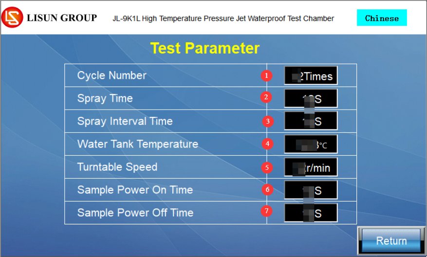
Note: Power On: The power-on duration covers the entire test period; power-off duration = 0 s. Power Off: The power-on duration = 0 s; the power-off duration covers the entire test period.
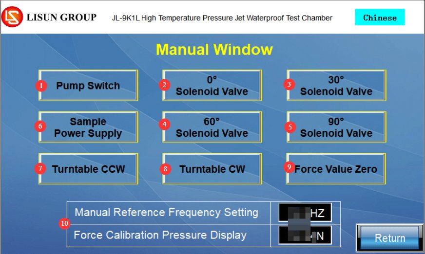
4.3 수동 창
그림 4-3를 참조하세요.
| 번호 | 주의 사항 |
|---|---|
| ① | 펌프 스위치 |
| ②③④⑤ | Nozzle Solenoid Valve: After starting the water pump, click the nozzle solenoid valve to activate the corresponding nozzle. |
| ⑥ | Sample Power Switch: Click to turn the sample power on or off |
| ⑦⑧ | Click to control the turntable’s forward/reverse rotation |
| ⑨ | Reset Pressure Value |
| ⑩ | Manual display of frequency and water pressure values for commissioning and testing water pressure |
5. IPX9K High-Temperature, High-Pressure Water Spray Test Procedure
5.1 Hydraulic Testing and Commissioning
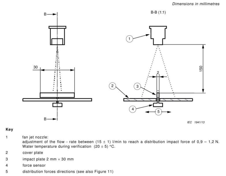
5.1.1 Standard Schematic Diagram
See Figure 5-1 for a schematic diagram illustrating the measurement of water jet impact force (adapted from IEC 60529, Figure 10).
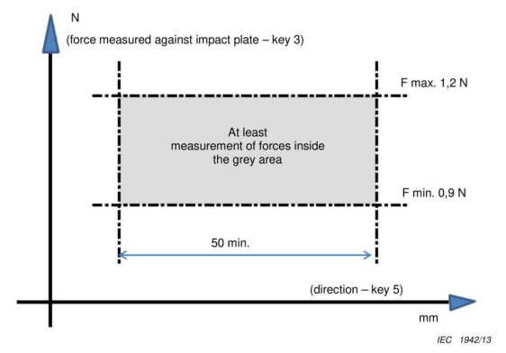
See Figure 5-2 for a schematic diagram of the impact force distribution (taken from IEC 60529, Figure 11).
5.1.2 Water Pressure Commissioning Procedures
| 명령 | 주의 사항 |
|---|---|
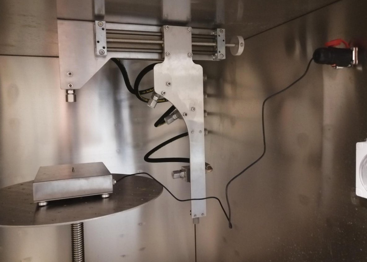
| ① | Connect the cable to the pressure calibration device and place it on the turntable, ensuring that its position and height comply with the standards, as shown in Figure 5-3. Then close the Basic door. |
| ② | Enter the manual mode, turn on the water pump switch, then open the solenoid valve for the 90° nozzle to ensure that the water jet from the nozzle strikes the pressure sensor at the center of the pressure calibration device. |
| ③ | Observe the current water injection pressure displayed in the manual window. If the pressure reading is too high, reduce the manual frequency by 0.1 or 0.2 each time; if the pressure reading is too low, increase the manual frequency by 0.1 or 0.2 each time. |
| ④ | Once the pressure meets the requirements—that is, when the reading stabilizes within the range of 0.9 N to 1.2 N—turn off the water pump switch and the 90° nozzle solenoid valve, then remove the pressure calibration device. |
5.2 Installing the Sample
5.2.1 Connecting the Sample Power Cord
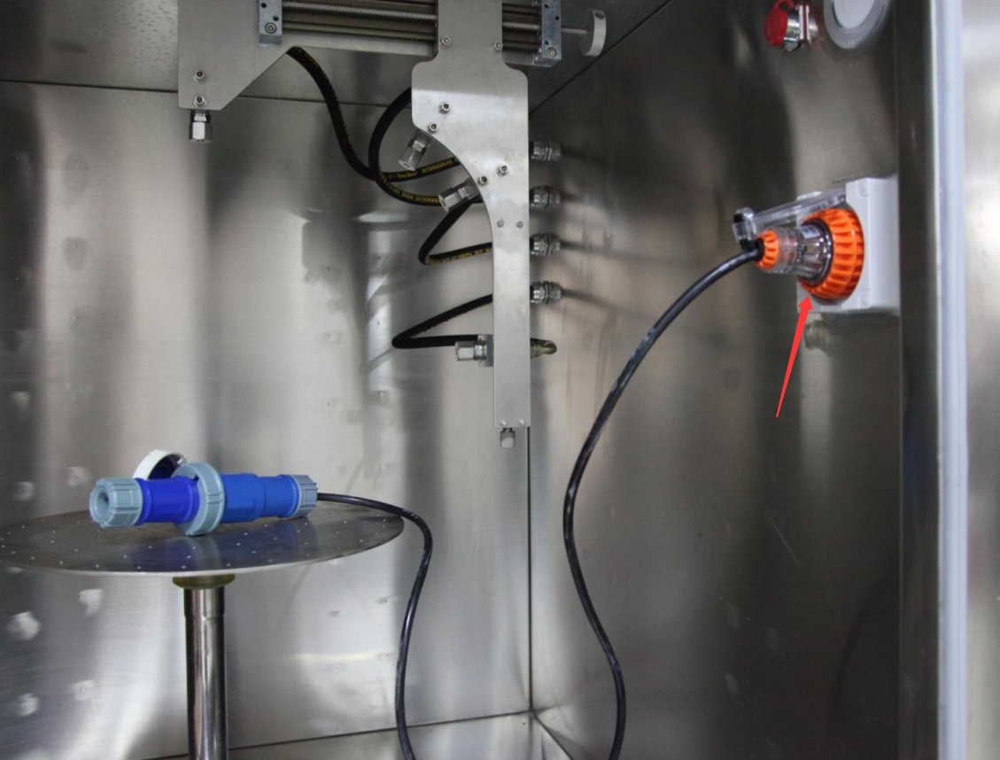
As shown in Figure 5-4, connect the sample power cord using the standard waterproof connector.
5.2.2 Schematic Diagram of Sample Installation
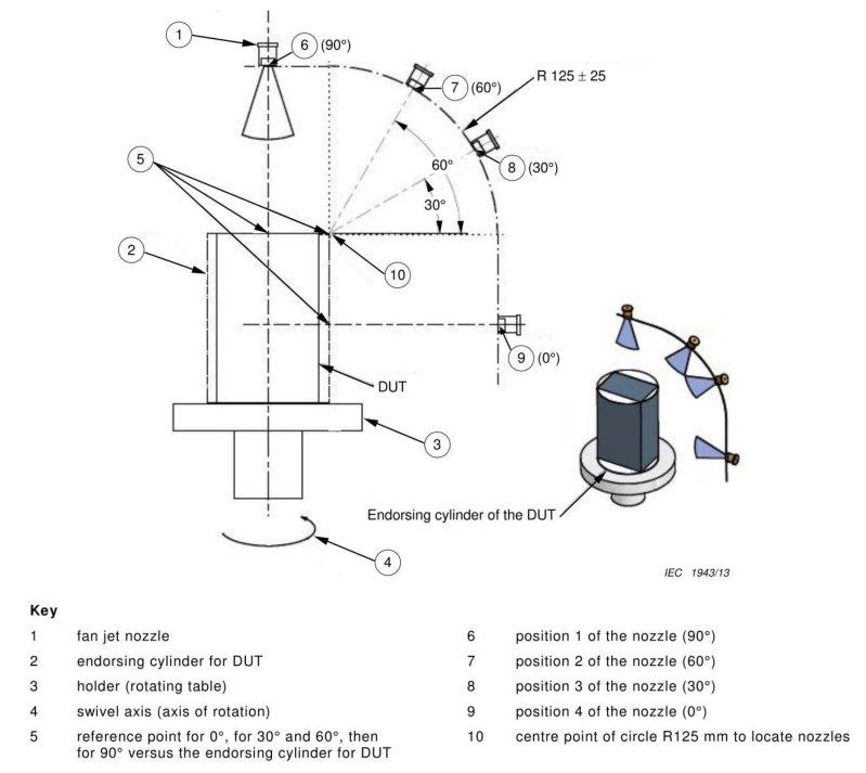
Install the specimen according to the standard, as shown in Figure 5-5. Ensure that the specimen is securely mounted to prevent it from falling during the test.
5.3 표준 테스트 매개변수
5.3.1 Standard Test Parameters for Small Specimens
Suitable for samples with maximum dimensions ≤250 mm, corresponding to Class A testing in GB/T 4208-2017 (IEC 60529:2013). The parameter settings are as follows: Number of cycles: 1; Spray duration: 30 s (per angle); Spray interval: 10 s; Water temperature: 80°C; Turntable speed: 5 r/min; Sample power status: Set according to test requirements; if no special requirements exist, set to continuously powered.
5.3.2 Standard Test Parameters for Large Specimens
Applicable to samples with a maximum dimension of ≥250 mm, corresponding to Class 14.2.9 testing in GB/T 4208-2017 (IEC 60529:2013). The test parameters are as follows: Test duration: Calculated based on the sample’s surface area, at a rate of 1 min/m², with a minimum of 3 min; Nozzle distance: Adjusted to 175 ± 25 mm; Water temperature: 80°C; Spray method: Manually adjust the nozzle angle to cover all external surfaces of the sample in sequence, ensuring the spray angle is as perpendicular as possible to the surface being tested; Rotating table: Select whether to enable or disable it based on the sample’s shape to ensure full surface coverage.
5.4 Start-up Test
5.4.1 프로 시저
| 번호 | 주의 사항 |
|---|---|
| ① | Make sure there is enough water in the tank; if not, press the “Add Water” button to refill it. |
| ② | Press the “Heat” button and wait for the water temperature to reach 80°C—this will take about 30 minutes. |
| ③ | Make sure Basic is securely closed, press the Reset button to clear the data from the previous test, and press the Start Test button to begin the test. |
| ④ | The equipment operates automatically according to the preset program: turntable begins rotating → 0° nozzle sprays for 30 seconds → spray pauses for 10 seconds → 30° nozzle sprays for 30 seconds → sprays at all four angles in sequence → cycle complete |
5.4.1 Key Points for Monitoring Operational Status
During the test, the following conditions are monitored in real time via the observation window and touchscreen: Water temperature: maintained within the range of 80±5°C; Pressure: maintained within the range of 8–10 MPa; Flow rate: maintained within the range of 14–16 L/min; Rotary table: Operates smoothly, without jamming or unusual noises; Samples: Securely fastened, with no shifting or detachment; Piping: No leaks or abnormal vibrations.
5.4.2 Pausing and Resuming Operations Midway
If you need to pause the test, click the “Stop Test” button; the equipment will immediately stop spraying and the turntable will stop rotating. After resolving the issue, click “Reset,” then click the “Start Test” button to resume the test. In the event of an emergency, press the emergency stop button to cut off power to the equipment. After resolving the issue, turn the emergency stop button clockwise to reset it, then resume the test.
5.5 테스트 종료
5.5.1 Safety Guidelines for Sample Retrieval
Do not open the chamber door fully immediately after the test is complete. First, open the door slightly to create a 5–10 cm gap to allow the high-temperature steam inside to escape. Wait 3–5 minutes for the chamber temperature to drop, then wear heat-resistant gloves to fully open the door. Disconnect the power supply to the test specimen first, then remove it and place it on a heat-resistant mat to cool naturally. Do not touch the inner chamber walls, nozzles, or other high-temperature components with bare hands.
5.5.2 Resetting Basic
After all tests are complete, press the “Heat” button again to turn off the heating function, and then turn off Basic.
5.5.3 Criteria for Evaluating Water Resistance
After the sample has cooled to room temperature, inspect and evaluate it in accordance with the requirements of the applicable standard: Check for water ingress inside the sample’s enclosure; if the amount of water entering the enclosure does not reach a harmful level, the sample is considered to meet the IPX9 standard; for samples tested under power, verify that their electrical functions are normal after the test.
6. 장비의 일상 유지보수 및 관리
6.1 Maintenance After Each Use
6.1.1 청소
Use a clean cloth to wipe away water stains from the inner walls of the chamber, the turntable, and the nozzle bracket; remove any debris, such as fallen sample labels or particles, from inside the chamber to prevent clogging of the water lines and filters; clean the viewing window glass and the wiper to maintain a clear view; and wipe down the exterior of the equipment to keep it clean and tidy.
6.1.2 Water Tank Maintenance
If Basic will be used again within a short period (within 7 days), the water in the tank may be left in the tank; if the chamber will not be used within 7 days, open the drain valve to empty the tank and remove any standing water from the pipes to prevent water quality deterioration and scale buildup.
6.2 정기 점검 일정
Perform tiered maintenance based on frequency and cycle of use:
| 유지보수 주기 | 유지 관리 프로젝트 | Key Points for Operation |
|---|---|---|
| 매주 | Visual and Piping Inspection | Clean the exterior of the equipment; check the pipe connections for leaks; ensure the drain is unobstructed |
| 월간 회원 | 필터 청소 | Remove the stainless steel filter from the water tank, clean out any debris, and reinstall it; clean the inside walls of the water tank. |
| 2 개월마다 | Deep Cleaning of the Water Tank | Drain the tank and thoroughly clean the scale and sediment from the inside walls of the tank. |
| XNUMX 개월마다 | 씰 검사 | Check the box door gaskets and pipe seals for signs of aging or damage. |
6.3 Specialized Maintenance of Core Components
6.3.1 High-Pressure Water Pump Maintenance and Oil Change
The high-pressure water pump is a core component of the equipment and requires periodic maintenance. After the pump has accumulated 500 hours of operation, the equipment will trigger a pump oil warning; the specialized oil must be replaced promptly.
| 단계 | 주의 사항 |
|---|---|
| ① | Tools needed: 19mm socket/adjustable wrench, oil pan, special-purpose motor oil, funnel |
| ② | Open the left side and rear cover of the unit, and locate the high-pressure water pump. |
| ③ | Unscrew the drain plug at the bottom of the water pump and use a drip pan to catch the waste oil. |
| ④ | Unscrew the oil fill plug at the top of the pump and wait until all the oil has drained out. |
| ⑤ | Reinstall the drain plug and tighten it, then add new motor oil through the fill port. |
| ⑥ | Check the liquid level window on the side of the pump; stop adding oil when the oil level reaches the red dot in the middle of the window. |
| ⑦ | Reinstall the fuel filler cap, clean up the work area, and complete the oil change. |
| ⑧ | Routine Inspection: Check the water pump daily for oil leaks or unusual noises; if any abnormalities are detected, shut down the machine immediately to address the issue. |
6.3.2 Nozzle Maintenance and Replacement
The nozzle is a precision standard component; do not knock or scratch the spray orifice; After each test, wipe water droplets from the nozzle surface to prevent scale buildup from clogging the spray orifices; if abnormal spray patterns, insufficient pressure, or significant flow rate deviations occur, check the nozzle for wear; if the nozzle is worn, it must be replaced with an original manufacturer’s standard nozzle to ensure that the spray parameters meet the standard requirements.
6.4 Maintenance of Idle Equipment
6.4.1 Short-term Idle Period (Within 1 Month)
Drain all standing water from the tank and water lines to prevent scale buildup on the nozzles and in the pipes; cover the entire unit with a dust-proof cloth to keep dust out; and store the unit in a dry, well-ventilated area.
6.4.2 Long-term inactivity (more than 1 month)
Complete all maintenance procedures for short-term storage; disconnect all electrical and water connections from the equipment; remove the water hoses, let them air dry, and store them properly; Apply a layer of rust-preventative oil to the inner walls of the water tank and the surfaces of metal parts to prevent rust; store the equipment in a cool, dry environment away from direct sunlight; apply a small amount of industrial lubricant to moving parts such as the turntable lead screw to prevent rust and jamming; Power on the equipment once a month, enter the manual control screen to test all functions, and shut it down after running for 5 to 10 minutes to prevent circuit deterioration.
6.5 교정 간격 요구 사항
To ensure the testing accuracy and operational reliability of Basic, it is recommended that calibration be performed periodically by a qualified third-party metrology organization. The recommended calibration interval is 12 months. The specific calibration interval may be determined by the user based on frequency of use, environmental conditions, and quality system requirements.
7. 문제 해결 및 일반적인 문제 해결 방법
| 결함 증상 | 가능한 원인들 | 순서 |
|---|---|---|
| 기기가 켜지지 않습니다 | Incorrect voltage, incorrect phase sequence | Check the product nameplate to ensure that both the input power supply voltage and frequency are correct; try again after swapping the connection order of any two phase wires. |
| No water is dispensed after pressing the “Add Water” button | Insufficient inlet water pressure | The water inlet of Basic requires a certain water pressure. If there is no water pressure, place the water tank in an elevated position to generate water pressure through the difference in water levels. |
| Nozzle pressure is too high, and flow rate is too low | 노즐 막힘 | Clean the nozzle and remove any debris from inside it |
| Nozzle pressure is too low, and flow rate is too high | Nozzle wear, pipe leaks | Check the nozzle hose for leaks; if the nozzle is worn and the orifice has become larger, replace it with a new one. |