
 영어
영어 中文简体
中文简体 Русский
 Español
 Português
 Türkçe
 العربية
 Deutsch
 Polski
 Italiano
 Français
 한국어
한국어 ไทย
ไทย Tiếng Việt
 日本語
日本語





























콘센트 핀 유지력 테스트 장치
사용자 설명서
적용 할 수있는 LISUN models: GNGPL-3607、LS-B12、LS-B12A、LS-B12B、LS-B12C
1. 장비에 대한 기본 이해
1.1 기본 속성
This device is intended for specific testing of the retention strength of plugs for household and similar uses.
It is primarily used in electrical product quality inspection laboratories, the quality control departments of plug manufacturers, third-party testing organizations, and for the inspection of products entering or leaving the country.
1.2 적용 가능한 표준
In strict accordance with Clause 24.11 and Figure 30 of GB/T 2099.1-2021, Clause 24.11 and Figure 33 of IEC 60884-1:2022, Clause 22.3 of GB/T 4706-2024, Clause 22.3 of IEC 60335-1:2016, Clause 12.11.1 and Figure 7 of BS 1363-1, Clause 13.4 of EN 50075, Clause 24.10 and Figure 31 of VDE 0620-2-1, and other relevant standards, and conducted testing.
In accordance with the tensile force values and application duration specified in the standard, a vertical tensile force is applied to the plug and prong test specimens under specific environmental conditions. The deformation and damage to the specimens are then observed to determine whether they meet the requirements of the standard.
1.3 전자 문서 다운로드
전자 사용자 설명서, 교정 인증서, 보증서 및 기타 문서의 다운로드 링크는 제품 발송 시 이메일로 이미 보내드렸습니다. 가능한 한 빨리 다운로드해 주시기 바랍니다. 만약 이메일을 받지 못하셨다면, 저희에게 연락하여 다운로드 링크를 다시 요청해 주십시오.
2. 사용상의 주의
2.1 운영 환경 안전 요구사항
Place the device on a level, stable workbench with at least 30 cm of clearance on all sides, away from sources of vibration.
2.2 작업자를 위한 안전 지침
Do not reach into the test area during testing to prevent crush injuries.
Samples must be securely positioned, and the weight clamps must firmly hold the pins in place to prevent the weights from falling off or popping out during testing, which could pose a safety hazard.
Conduct testing strictly in accordance with the standards. Do not add weights without authorization to prevent equipment damage and safety incidents.
3. 테스트 설정 소개
그림 3-1를 참조하세요.
| 번호 | 주의 사항 |
| ① | Steel plate with test holes; the diameter of the test holes is customized according to the applicable standard. |
| ② | Weights, which provide a constant vertical test force; the weights are customized according to the corresponding standards. |
| ③ | Weight clamp—used during testing to secure weights and apply tension to the pin |
| ④ | Adjustable base to ensure the unit is placed level |
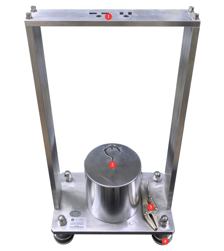
그림 3-1
4. Latch Strength Test
4.1 표본 선정
Select brand-new, unused finished plugs that have not undergone any destructive testing, and exclude any nonconforming specimens with surface dents, cracks, or obvious deformation.
4.2 Confirmation of Test Standards and Parameters
4.2.1 Basis for the Standard
Note: This test procedure uses Clause 24.11 of IEC 60884-1:2022 as an example. Test procedures may vary slightly across different standards; please strictly follow the applicable standards for the product and the target market when conducting tests.
4.2.2 테스트 매개변수
See Figure 4-1 (taken from the IEC standard) for a diagram illustrating the interrelationship between plug pins, test holes, and tensile force P.
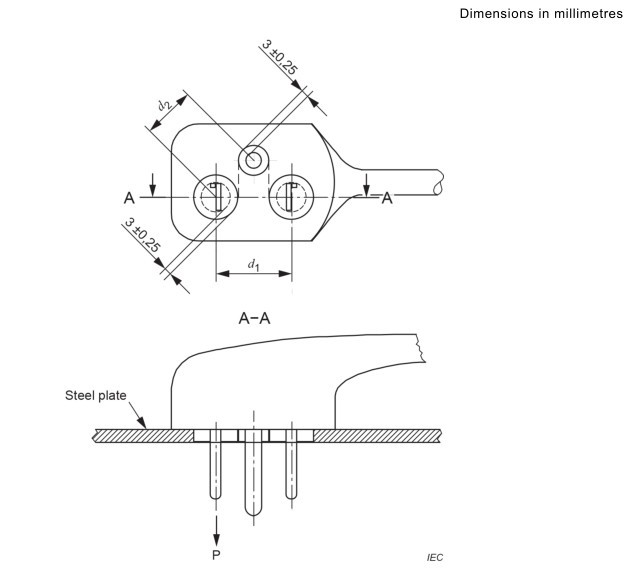
그림 4-1
The tensile force shall comply with the maximum pull-out force specified in Table 19 of this standard; see Figure 4-2 (taken from the IEC standard).
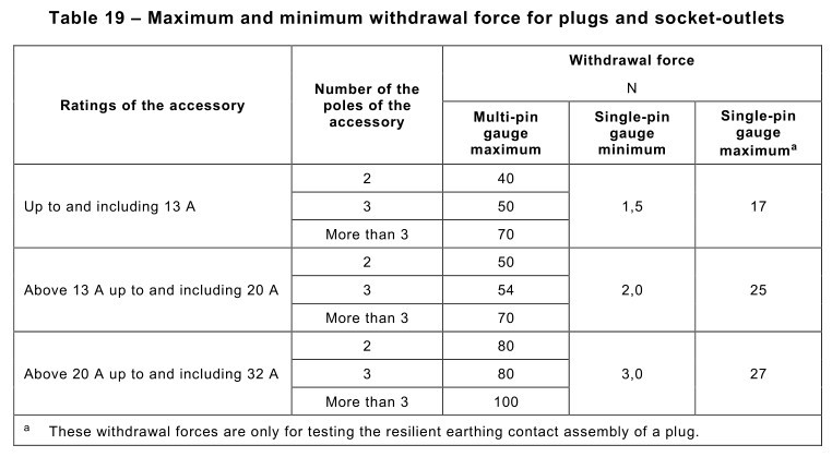
그림 4-2
4.3 Practical Experiment
The plug shall be placed in a High Temperature Chamber maintained at a stable temperature of (70±2) °C for 1 hour. Then, in accordance with 4.2.2, the test specimen shall be securely clamped inside the High Temperature Chamber for testing and shall not be removed from the Chamber.
Apply a tensile force P to each pin sequentially along the pin’s longitudinal axis for 1 minute; no impact is permitted during this process. See Figure 4-3 for a schematic diagram of the application of tensile force P to the LS-B12.
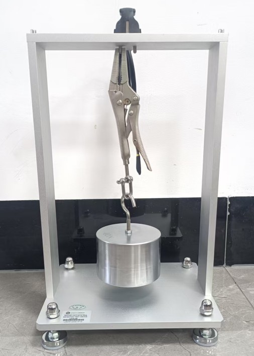
그림 4-3
4.4 시험 결과 해석
After the test is complete, remove the device and the test specimen plug from the test chamber and allow them to cool to ambient temperature. If it is verified that the displacement of any pin in the plug body does not exceed 1 mm, the test specimen passes this test.
5. 테스트 후 절차
5.1 장치 재설정
When the device is not in use, do not load it with test specimens or weights, and avoid applying force to it.
5.2 샘플 준비
시험에 합격한 샘플과 불합격한 샘플을 분리하고, 명확하게 표시하여 혼동을 피하십시오.
5.3 시험장 청소 및 정리
Use a lint-free, soft cloth to wipe away dust and debris from the surfaces of the steel plate, brackets, weights, weight clamps, and other components. Do not rinse the equipment directly with water.
Tidy up the workbench and remove any debris left over from the experiment.
6. 정기 유지보수 및 관리
6.1 정기 점검
Depending on the storage environment of the device, periodically apply rust-preventive oil to all components of the device—especially the test holes in the steel plates, the weights, and the clamps—to prevent rust.
6.2 교정 주기 요구사항
To ensure the device’s measurement accuracy and operational reliability, it is recommended that it be sent periodically to a qualified third-party metrology organization for calibration. The recommended calibration interval is 12 months. Users may determine the specific calibration interval based on frequency of use, environmental conditions, and quality system requirements.
7. 문제 해결 및 일반적인 문제 해결 방법
| 결함 증상 | 가능한 원인들 | 순서 |
| The clamp doesn’t hold securely; the weight falls off | The device was not placed level, preventing the clamp from engaging with the latch. | If the device is tilted, it will not only affect the test results, but the weights may also fall off during the test; please reinstall the device and level it before retrying. |