
 영어
영어 中文简体
中文简体 Русский
 Español
 Português
 Türkçe
 العربية
 Deutsch
 Polski
 Italiano
 Français
 한국어
한국어 ไทย
ไทย Tiếng Việt
 日本語
日本語





























덮개 및 덮개판 검증용 시험 장치
사용자 설명서
적용 할 수있는 LISUN models: LS-B14
1. 장비에 대한 기본 이해
1.1 기본 속성
1.1.1 응용 시나리오
This device is intended for specialized testing of the mechanical strength of sockets, switches, and other covers or faceplates for household and similar uses.
It is primarily used in electrical product testing laboratories, the quality control departments of socket and electrical equipment manufacturers, third-party testing organizations, and for import and export product inspections.
1.1.2 적용 가능한 표준
In strict accordance with clauses 24.15 through 24.17 and Figure 31 of GB/T 2099.1-2021, “Plugs and Sockets for Household and Similar Purposes—Part 1: General Requirements” (IEC 60884-1:2022, Clauses 24.13 through 24.15 and Figure 34), GB/T 16915.1, Clauses 20.4 through 20.6 and Figure 19 (IEC 60669-1, Clauses 20.5 through 20.7 and Figure 13), and testing was conducted accordingly.
1.2 Test Principles
1.2.1 Principles of Mechanical Pressure
Using a high-precision push-pull force gauge, the system applies a stable and precise push-pull force to the lid or cover plate in accordance with standard requirements.
1.2.2 Principles of Diagnostic Testing
After the force application time specified in the standard has elapsed, observe whether the cover or cover plate has come off, and determine whether its mechanical strength meets the requirements by referring to national or international standards.
1.3 Equipment Configuration Verification
1.3.1 포장 풀기
When unpacking the device, handle it gently to avoid scratching the exterior casing with sharp tools. After unpacking, first inspect the exterior of the device to ensure there are no visible deformations, dents, or damage. If you notice any abnormalities with the device or its accessories, please contact us immediately.
1.3.2 본체 및 부속품
| 번호 | 주의 사항 |
| ① | LS-B14 main unit, including a cover plate mounting position and a push-pull force gauge (0–200 N, resolution 0.01 N, accuracy <±1%) |
| ② | Rigid Material Sheet (1 mm ± 0.1) |
| ③ | Force Gauge Accessory Kit |
1.3.3 전자 문서 다운로드
We have already sent the download links for the electronic user manual, calibration certificate, warranty card, and other documents via email at the time of shipment. Please download them promptly. If you have not received the email, please contact us to request the download links again.
2. 사용상의 주의
2.1 Operating Environment Safety Requirements
Operating environment temperature: 10°C to 35°C; relative humidity: 45% to 75%; no condensation, no corrosive gases, and no airborne dust.
Place the device on a level, stable workbench with at least 30 cm of clearance on all sides, away from sources of vibration.
2.2 Safety Guidelines for Operators
During testing, do not extend any body parts into the test area to prevent crush injuries.
Samples must be securely positioned to prevent them from falling or flying out during the application of force, which could pose a safety hazard.
Conduct tests strictly in accordance with the force values specified in the standards; do not increase the force values without authorization to prevent equipment damage and safety incidents.
3. Introduction to the Test Setup
그림 3-1를 참조하세요.
| 번호 | 주의 사항 |
| ① | Push-Pull Gauge, with thrust test accessories installed by default |
| ② | Handwheel for controlling the height and force reading of the push-pull force gauge |
| ③ | Solid wood panel, used for mounting the installation box and its cover or faceplate |
| ④ | Adjustable base to ensure the unit is level |
| ⑤ | 경질 보드 재료 |
| ⑥ | Force Gauge Accessory Kit, containing standard accessories for the force gauge |
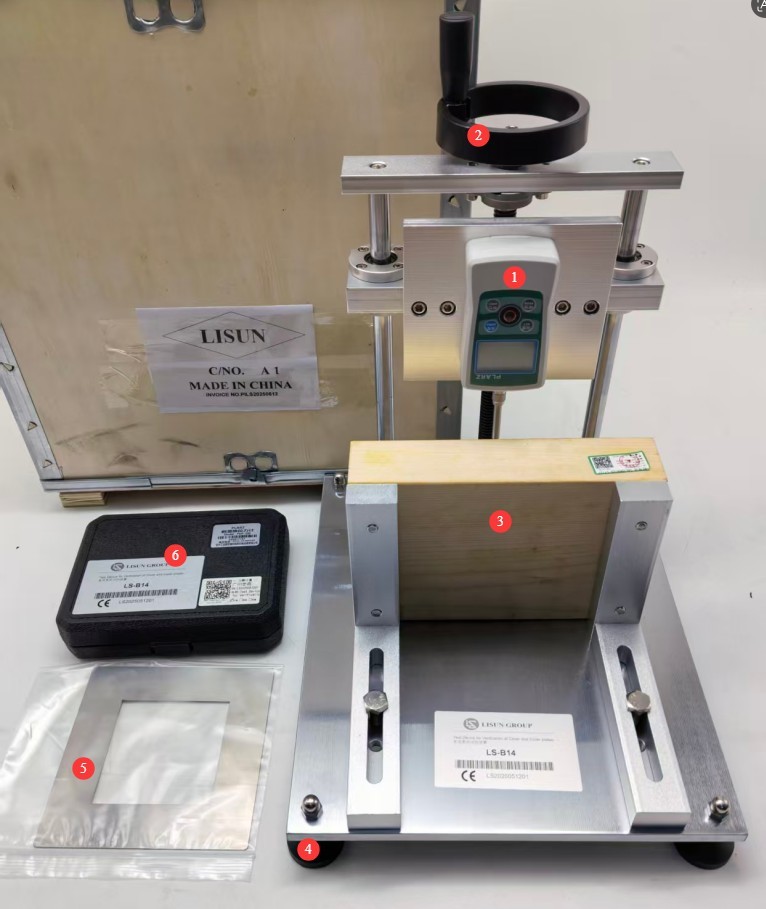
그림 3-1
4. Mechanical Strength Test for Lids or Cover Plates
4.1 샘플 전처리
Select brand-new, unused finished product specimens that have not undergone any destructive testing, and reject any nonconforming specimens with surface dents, cracks, or obvious deformation.
If a specific test temperature is required, allow the test specimen to stand for 30 minutes under standard test conditions so that its temperature matches the ambient temperature, thereby preventing temperature differences from affecting the test results.
4.2 시험 절차
| 명령 | 주의 사항 |
| ① | Refer to the relevant provisions of the standard to determine whether rigid board material needs to be installed. |
| ② | Determine whether a mounting box is needed. If so, refer to Figure 4-1 to cut an appropriate hole in the mounting box. |
| ③ | The push-pull tester comes standard with a thrust test setup, but this can be replaced with another test setup if needed. |
| ④ | Install the cover or cover plate, adjust the position of the specimen and the height of the push-pull force gauge so that the specimen and the push-pull force gauge are in the test-ready position. Refer to Figure 4-2. |
| ⑤ | Turn on the push-pull force gauge, verify that the reading is correct, and perform a “zeroing” operation if necessary. |
| ⑥ | Refer to the relevant standard provisions, use the handwheel to control the applied force, and begin the test. |
| ⑦ | If the cover plate falls off during the test, the test is terminated; otherwise, once the force application time meets the standard requirements, use the handwheel to stop the push-pull tester. |
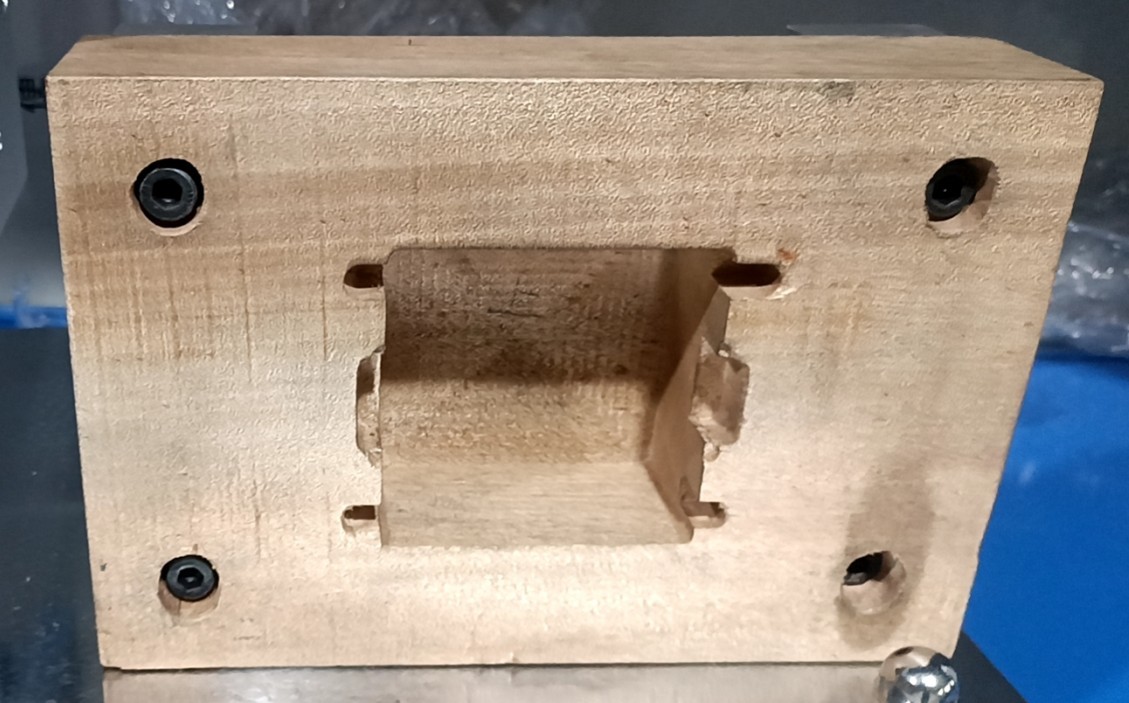
그림 4-1
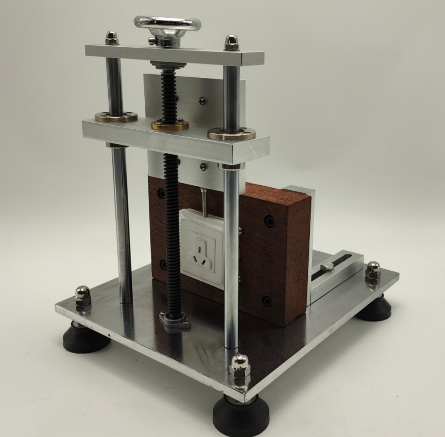
그림 4-2
4.3 시험 결과 해석
Determine whether the mechanical strength of the test specimen meets the requirements by referring to the corresponding provisions of the standard.
5. 테스트 후 절차
5.1 Device Reset
Reset the force gauge to prevent the application of force when not testing. Then turn off the force gauge.
5.2 샘플 준비
Separate the samples that passed and failed the test, label them clearly, and avoid mixing them up.
5.3 Cleanup and Organization of the Test Site
Use a lint-free, soft cloth to wipe away dust and debris from the bracket, handwheel, and the surface of the unit. Do not rinse the equipment directly with water.
Tidy up the workbench, arrange items neatly, and clean up any debris generated during the experiment.
6. 정기 유지보수 및 관리
6.1 정기 점검
Every 3 months, apply a small amount of neutral lubricating grease to key components, such as handwheel shafts, bearings, and slide rails, to prevent rust and binding.
6.2 교정 주기 요구사항
기기의 정확성과 신뢰성을 보장하기 위해, 공인된 제3자 계측 연구소에 정기적으로 보내 교정을 받는 것이 좋습니다. 권장 교정 주기는 12개월입니다. 사용자는 사용 빈도, 환경 조건 및 품질 시스템 요구 사항을 고려하여 구체적인 교정 주기를 결정할 수 있습니다.
7. Troubleshooting and Resolution of Common Problems
| 결함 증상 | 가능한 원인들 | 순서 |
| The stand jerks when raising and lowering | Dust buildup on the handwheel shaft or slide rod, insufficient lubrication, or foreign objects lodged in the mechanism | Try again after removing dust, replenishing lubricant, and clearing any foreign objects from the gaps. |