
 영어
영어 中文简体
中文简体 Русский
 Español
 Português
 Türkçe
 العربية
 Deutsch
 Polski
 Italiano
 Français
 한국어
한국어 ไทย
ไทย Tiếng Việt
 日本語
日本語





























산소 폭탄 공기 노화 시험 챔버
사용자 설명서
적용 할 수있는 LISUN models: LS-B48
1. 장비에 대한 기본 이해
1.1 주요 기술 사양
| Air Spring Aging Test | The medium is air, the temperature is 127°C, and the operating pressure is 0.55 ± 0.02 MPa (in accordance with standards such as GB/T 2951.12, Section 8.2) |
| Oxygen Cylinder Aging Test | The medium is oxygen with a purity of not less than 97%, at a temperature of 70°C and an operating pressure of 2.1 ± 0.07 MPa (in accordance with standards such as GB/T 2951.12, Section 8.3). |
| 업무 관련 스트레스 | 2.5MPa 이하 |
| 압력 표시 정확도 | 0.02 MPa의 |
| 온도 제어 범위 | 실온 ~ 150°C |
| 온도 편차 | ± 0.5 ° C |
| 캐비닛 치수 | 840 420 × × 880 MM |
| 탱크 용량 | ≥4000 cm³ |
| Voltage Reduction Procedure | After the test is complete, the test chamber is automatically depressurized in stages for a period of no less than 5 minutes, until the pressure drops to atmospheric pressure. |
| 내장 타이머 | 0.01 s to 999.9 s/m/h—any value can be set |
| 전원 공급 전압 | 교류 220~240V, 50/60Hz |
| 공기 공급 | Customer-supplied: compressed air and oxygen with a purity of at least 97% |
1.2 Equipment Purpose and Applicable Standards
1.2.1 Purpose of the Equipment
This equipment is designed for conducting aging tests on medical device materials, rubber (plastic, artificial leather) insulation and sheathing for wires and cables, as well as other polymeric materials. These tests are performed under specified pressure and temperature conditions using compressed air (air cell) or oxygen (oxygen cell) as the test medium to evaluate changes in material performance following aging.
1.2.2 표준 준수
National Standard: GB/T 2951.12, Section 8.2 (Air-Chamber Aging), Section 8.3 (Oxygen-Chamber Aging);
National Standard: GB/T 4706.1, Clause 22.32 (General Safety Requirements for Household and Similar Electrical Appliances);
National Standard: GB/T 5013.1 (Rubber-Insulated Cables with Rated Voltages of 450/750 V and Below—Part 1: General Requirements);
Corresponding international standards: IEC 60811-1-2, Clauses 8.2 and 8.3; IEC 60335-1, Clause 22.32.
1.3 Unboxing Inspection and Verification of Accessories
1.3.1 포장 해제 및 육안 검사
When unpacking the equipment, handle it gently to avoid scratching the exterior casing with sharp tools. After unpacking, first inspect the exterior of the device to ensure there are no obvious deformations, dents, or peeling paint, and that the panel instruments and buttons are not damaged or loose. If you discover any damage or deformation to the device or its accessories, do not power it on. Contact LISUN 고객 서비스 담당자가 즉시 응대합니다.
1.3.2 Host Classes
1 main unit of an Oxygen Bomb Air Aging Test Chamber.
1.3.3 소모품 및 액세서리
Standard accessories include: an adjustable wrench, an Allen wrench, an intake pipe, and two spare rubber gaskets (one large and one small).
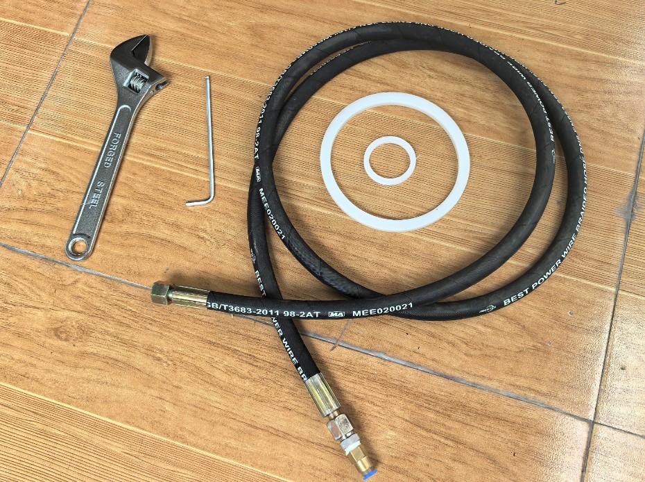
그림 1
Download links for the digital user manual, warranty card, and other documents have been sent to you via email. Please download them as soon as possible. If you missed the email, please feel free to contact us to request the download links again.
1.4 장비 구조 설명
Front of the test chamber: ① Touchscreen; ② Sealing cover; ③ The overpressure protection device is attached to the top of the sealing cover.
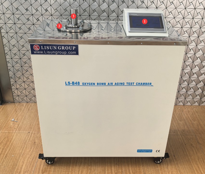
그림 2
Side of the test chamber: Equipment power switch.
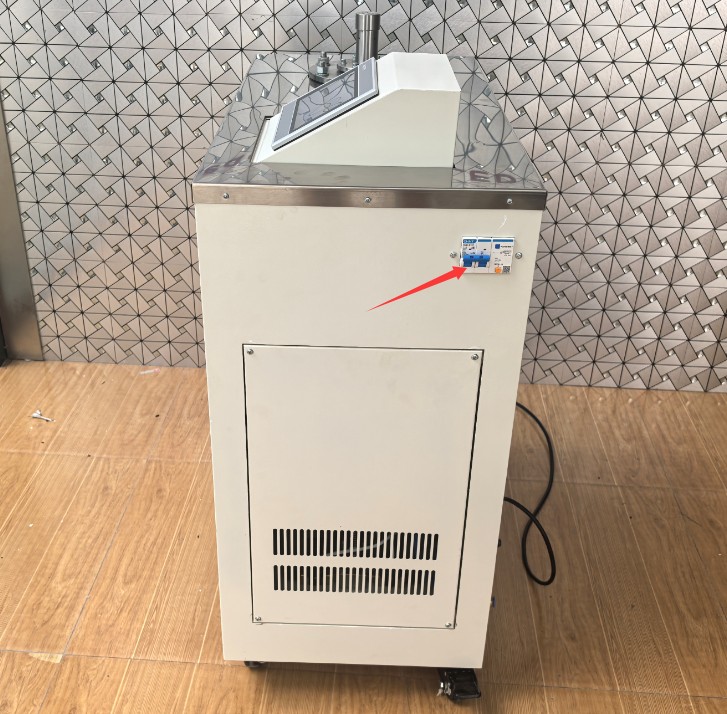
그림 3
Rear of the test chamber: ① Air inlet; ② Air outlet; ③ Power cord.
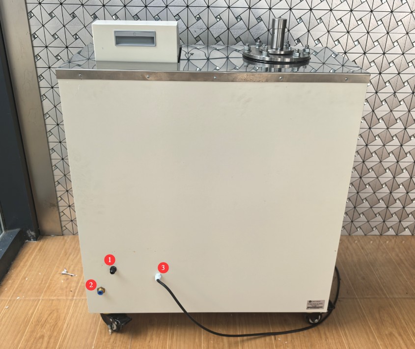
그림 4
2. 안전상의 주의
2.1 Power Supply and Grounding Safety
2.1.1 Power Connection Requirements
You must use a dedicated power source that matches the device’s rated voltage (AC 220–240 V, 50/60 Hz). Never share an outlet with other high-power devices.
Power lines must be rated for the equipment’s power consumption to prevent overloading; when the equipment is not in use, all power sources (including the main power switch and the air supply valve) must be turned off.
2.1.2 접지 요구 사항
The equipment must be reliably grounded (grounding resistance ≤ 4 Ω). The grounding conductor must be connected separately; it is strictly prohibited to share it with the neutral wire to prevent electric shock caused by leakage current.
Before each test, check the grounding wire for any looseness or damage; if any issues are found, repair them before use.
2.2 작동 중 안전 예방 조치
2.2.1 Precautions for Operating the Sealing Cover
Before installing or removing the seal cap, you must ensure that the temperature inside the tank is ≤40°C. If the temperature is too high during operation, any resulting damage to the equipment will not be covered under warranty.
Before removing the seal cap, ensure that the pressure gauge reads 0 MPa (atmospheric pressure). The manufacturer assumes no liability for personal injury or equipment damage resulting from removal under high-pressure conditions.
2.2.2 Contraindications During the Test Procedure
During the test, do not open the tank door or touch the pressure vessel to prevent burns or impact injuries caused by the leakage of high-temperature, high-pressure media.
Materials with substantially different compositions must not be tested together in the same container to prevent them from influencing each other and causing inaccurate test results.
The test specimens must not occupy more than 1/10 of the tank’s effective volume, and the specimens must not touch each other or the tank wall to prevent localized overheating or uneven stress distribution.
2.3 Environmental Safety Requirements
2.3.1 Environmental Restrictions for Placement
The equipment must not be stored or used in the following environments:
Environments containing flammable or explosive vapors (such as those near flammable substances like alcohol or gasoline);
Environments with direct sunlight, high humidity (relative humidity > 85%), or corrosive air;
Unstable work surfaces (such as wobbly workbenches) or areas with heavy dust.
2.3.2 환경 요구 사항
A working space of at least 50 cm must be left around the equipment to facilitate wiring, air supply connections, and maintenance;
Avoid placing clutter near the equipment, especially conductive or flammable items, to prevent accidents.
2.4 비상 대응
2.4.1 Handling Pressure Anomalies
If the pressure inside the tank suddenly exceeds the set value and the overpressure protection device does not activate, immediately shut off the power and gas supply, manually open the relief valve to slowly relieve the pressure (for at least 5 minutes), and inspect the equipment once the pressure has dropped to 0 MPa.
If the pressure cannot reach the set value, stop the test first, check whether the seals are damaged and whether there is sufficient air supply, and restart the test after resolving the issue.
2.4.2 Handling Temperature Anomalies
If the temperature exceeds the set value by more than 5°C and the equipment does not automatically stop heating, immediately disconnect the power supply. Once the temperature has dropped to room temperature, inspect the heater and the PLC control system, and contact the manufacturer for repairs (non-professionals must not disassemble the equipment).
2.5 기타
본 설명서에 나와 있지 않은 사항에 대해서는 주의를 기울여 진행하시거나 당사에 문의해 주십시오.
3. 시험 전 준비 사항
3.1 장비 점검
3.1.1 Visual and Component Inspection
Check the tank and the electrical control cabinet enclosure for any deformation or damage.
Inspect the seals (large and small O-rings): Check for signs of aging, damage, or deformation; if any are found, replace them immediately (the parts list includes spare O-rings). Inspect the high-pressure air hose to ensure it is in good condition, with no signs of aging, rust, or air leaks (apply soapy water to the connections and check for bubbles).
3.1.2 Instrument and Circuit Inspection
Check the power cord, ground wire, and wiring for damage.
Turn on the power switch (just to power up the unit—do not start the test), and check that the touchscreen, pressure gauge, and temperature gauge are displaying normally, with no garbled characters or a black screen.
3.2 샘플 준비
3.2.1 시료 선택 및 준비
Prepare test specimens in accordance with the test standards (such as Chapter 9 of GB/T 2951.11-2008), ensuring that the specimen surfaces are free of oil, impurities, and damage, and that their dimensions meet the test requirements.
Selection of Test Specimens: Materials with the same or similar compositions shall be grouped together; materials with substantially different compositions (such as rubber and plastic) shall not be tested in the same group.
3.2.2 Requirements for Sample Placement
Remove the six screws on the outside and open the seal cover:
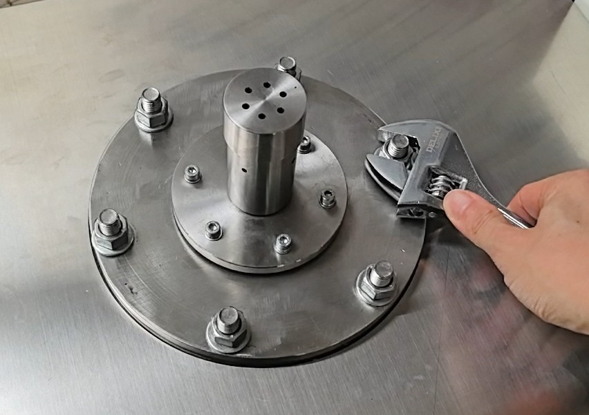
그림 5
Remove the internal specimen holder:
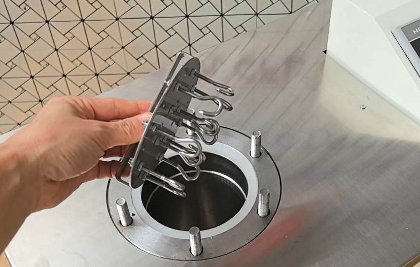
그림 6
Hang the prepared specimens on the specimen rack, ensuring that the specimens do not touch each other and that they do not come into contact with the inner wall of the pressure vessel.
After placing the specimen holder in the pressure vessel, verify that the total volume occupied by the specimens is ≤ 1/10 of the vessel’s effective volume (this can be estimated based on a vessel volume of ≥ 4000 cm³, with the total specimen volume ≤ 400 cm³).
Then tighten the seal cap again.
3.3 Preparing the Gas Supply
3.3.1 Preparing the Air Spring Air Source
Prepare oil-free, moisture-free compressed air using your own air compressor. The compressor must be drained and have its oil changed regularly to ensure a clean air supply.
Connect one end of the intake tube to the equipment’s intake port, and tighten the connection to prevent air leaks:
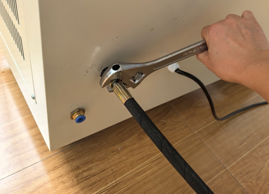
그림 7
The other end is connected directly to the air compressor.
3.3.2 Preparation of the Oxygen Bomb Gas Source
Prepare industrial oxygen with a purity of ≥97%. Use oxygen cylinders equipped with pressure-reducing valves (which must be calibrated and certified); the output pressure of the pressure-reducing valve must not exceed 2.5 MPa. Avoid feeding oxygen directly into the equipment at high pressure.
To perform an oxygen bomb aging test, remove the top of the other end of the intake pipe so it can be connected to the oxygen cylinder regulator:
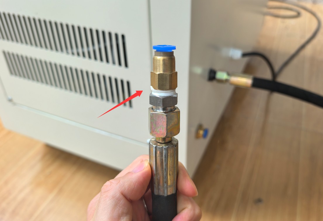
그림 8
4. Touchscreen Program Operation of The Oxygen Bomb Air Aging Test Chamber
4.1 Introduction to the Touchscreen Interface
Initial Screen: ① Switch between Chinese and English; ② Display of automatic valve on/off and heating on/off statuses; ③ Display of the pressure tank’s current pressure, current temperature, and current pressure-holding time; ④ Buttons for automatic test start and manual venting; ⑤ Parameter settings.
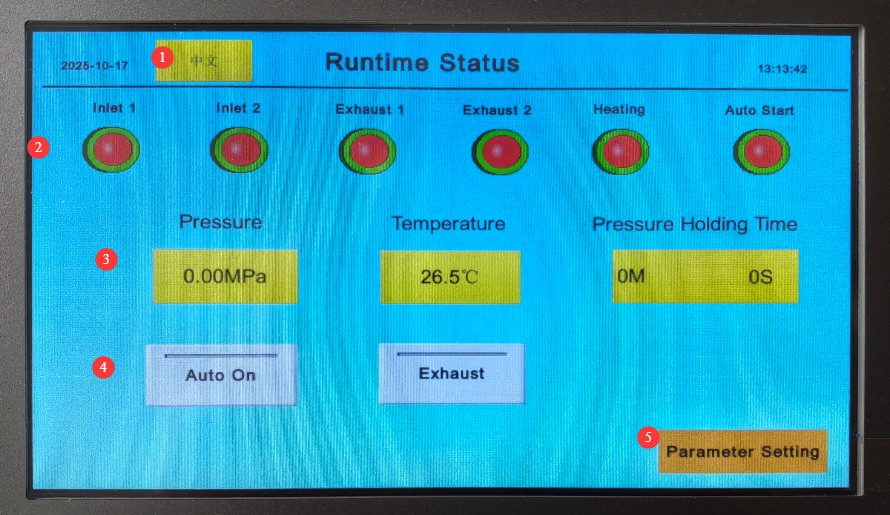
그림 9
Access the parameter settings screen: ① Heating temperature; ② Pressure setting; ③ Venting frequency; ④ Inlet flow frequency; ⑤ Pressure hold time; ⑥ Automatic venting pressure; ⑦ Rapid venting time; ⑧ Rapid venting pressure; ⑨ Factory settings (normally do not need to be accessed); ⑩ Return to the initial screen.
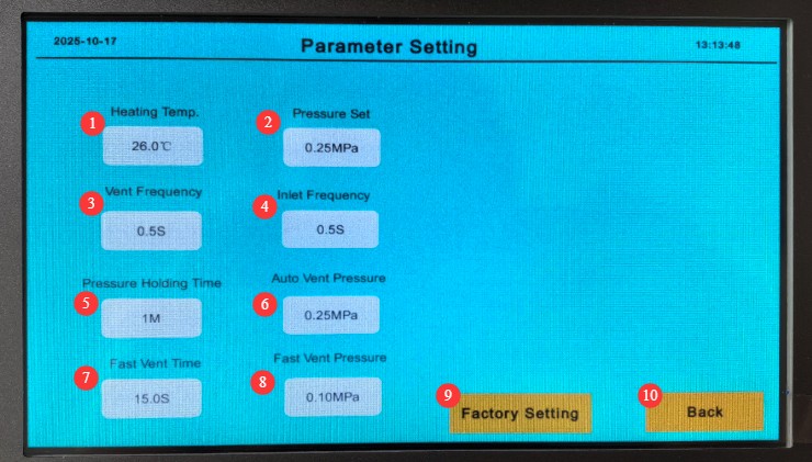
그림 10
4.2 Test Parameter Settings (by air bomb/oxygen bomb)
4.2.1 Setting Test Parameters for the Air Spring Test
Set the parameters according to the following requirements:
Heating temperature: 127°C (tolerance ±0.5°C, automatically controlled by the equipment);
Pressure setting: 0.55 MPa ± 0.02 MPa;
Deflation rate: Default 0.5 seconds (the lower the number, the faster the deflation rate. The standard specifies that the deflation time must not be less than 5 minutes; the deflation rate can be fine-tuned based on actual conditions)
Injection frequency: Default 0.5 seconds (during the test, the system first fills the chamber to 90% of the target pressure, then fills the remaining 10% intermittently at a frequency of 0.5 seconds until the set pressure is reached);
Pressure-holding time: Set according to specific test requirements (e.g., 5 minutes, adjusted using a timer);
Automatic pressure relief: Must match the set pressure value (once the pressure reaches the set value, the pressure vessel will begin to heat up; as it heats up, the pressure inside the vessel will increase; once it exceeds this set value, the pressure vessel will automatically relieve pressure until the set value is reached again).
Rapid Deflation Time: Default 15 seconds (During deflation, when the pressure reaches the rapid deflation pressure value, the pressure tank will release all air pressure within 15 seconds);
Quick-release pressure: Default setting; no changes needed;
Once you’ve finished setting it up, tap “Back” to return to the main screen.
4.2.2 Setting Parameters for the Oxygen Bomb Test
Set the parameters according to the following requirements:
Heating temperature: 70°C (tolerance ±0.5°C, automatically controlled by the equipment);
Pressure setting: 2.1 MPa ± 0.02 MPa;
Deflation frequency: Default 0.5 seconds (the smaller the number, the faster the deflation rate. The standard specifies that the deflation time must not be less than 5 minutes; the deflation frequency can be fine-tuned based on actual conditions)
Injection frequency: Default 0.5 seconds (During the test, the system first fills the chamber to 90% capacity, then fills the remaining 10% intermittently at a frequency of 0.5 seconds until the set pressure is reached);
Pressure-holding time: Set according to specific test requirements (e.g., 5 minutes, adjusted using a timer);
Automatic pressure relief: Must match the set pressure value (once the pressure reaches the set value, the pressure tank will begin to heat up; as it heats up, the pressure inside the tank will increase; once it exceeds this set value, the pressure tank will automatically relieve pressure until the set value is reached again).
Rapid Deflation Time: Default 15 seconds (During deflation, when the pressure reaches the rapid deflation pressure value, the pressure tank will release all air pressure within 15 seconds);
Quick-release pressure: Default setting; no changes needed;
Once you’ve finished setting it up, tap “Back” to return to the main screen.
4.3 Test Run Control
4.3.1 Startup Test Procedure
Verify that the gas source is connected (connect the air cylinder to the air compressor; connect the oxygen cylinder to the oxygen tank), and open the gas source valve (start the air compressor; set the pressure regulator on the oxygen tank to a pressure slightly higher than the set pressure);
Tap the “Start Automatic Test” button on the main screen to begin running the device;
Automatic Equipment Process: Inject gas (internal tank pressure rises to the set value) → Start heating (temperature rises to the set value) → Pressure-holding timer (pressure is automatically released after the set pressure-holding time is reached);
During the test, real-time changes in temperature, pressure, and elapsed time can be monitored without the need for manual intervention.
4.3.2 Test Pause/Emergency Stop
If you need to pause the test (e.g., for a temporary adjustment), click the “Automatically Start Test” button again to stop the device. The device will stop introducing gas and heating, and the pressure will be maintained. Then, press “Manual Vent” to quickly release the pressure in the pressure vessel. To resume, simply click “Automatically Start Test” again.
In the event of an emergency (such as abnormal pressure or temperature), immediately click the “Automatically Start Test” button again to stop the equipment, or shut off the main power supply to halt all equipment operations. Then, follow the procedures outlined in “2.4 Emergency Response.”
5. 테스트 후 절차
5.1 Automatic Equipment Cleanup Process
5.1.1 Automatic Pressure Relief and Cooling
When the pressure-holding period ends, the equipment automatically initiates the pressure-release procedure, which lasts for at least 5 minutes (to prevent the formation of gas pores in the specimen), and the pressure is gradually reduced to 0 MPa;
When the pressure-holding timer expires, the heater automatically shuts off, and the temperature inside the tank begins to cool down naturally, without the need for manual intervention.
5.1.2 Status Confirmation
Observe the status monitoring area on the touchscreen: The pressure is displayed as 0 MPa, and the temperature has dropped below 40°C. Confirm that the equipment has completely stopped operating (none of the “Heating,” “Air In,” or “Air Out” indicator lights are on).
5.2 Manual Follow-Up Actions
5.2.1 Turn Off the Gas Supply and Power Supply
Close the air supply valve: For air-powered cartridges, shut off the air compressor; for oxygen-powered cartridges, close the oxygen cylinder valve (and loosen the pressure regulator);
Then turn off the main power switch for the equipment.
Disconnect the high-pressure air hose (if the equipment will not be used for an extended period).
5.2.2 Removal of the Sealing Cap and Extraction of the Specimen
Use an adjustable wrench to gently loosen the fasteners on the seal cap, then remove the seal cap (be sure to wear hand protection to avoid burns from residual heat);
Remove the sample holder, take the sample off the holder, and place it in a designated container to prevent contamination or damage to the sample.
5.3 Post-Test Treatment of Specimens
5.3.1 Requirements for Sample Placement
Place the removed test specimens at ambient temperature (23±2°C), away from direct sunlight, and leave them for at least 16 hours (in accordance with the requirements of GB/T 2951.12). Once the properties of the test specimens have stabilized, proceed with subsequent testing (such as tensile and dielectric property tests).
5.3.2 Cleaning the Sample Holder and the Vessel
Wipe the specimen holder with a clean cloth to remove any residual impurities from the specimen;
If there is a small amount of dust inside the tank, open the tank door to ventilate the area and clean the interior with a dry brush. Do not use water or detergents (to prevent damage to the heating element and corrosion of the stainless steel tank).
6. 장비의 일상 유지보수 및 관리
6.1 Daily Maintenance (Once Before and Once After Each Test)
6.1.1 Appearance and Cleaning
Wipe down the equipment housing, touch screen, and pressure gauge with a dry cloth to remove dust and grease, ensuring that the interfaces are clear and the components are free of debris;
Check the high-pressure air hose connections for signs of air leaks (such as bubbles in soapy water); if any are found, tighten the connections or replace the gaskets.
6.1.2 Inspection of Seals
Inspect the large and small O-rings on the sealing cap: Check for deformation, cracks, or sticking. If the surface is greasy, wipe it clean with a clean paper towel; if damaged, replace them promptly with the spare O-rings (the parts list includes one of each).
6.2 Weekly Maintenance (Once a Week)
6.2.1 Wiring and Grounding Inspection
Open the side door of the electrical control cabinet (after turning off the power), check whether the internal terminal blocks are loose and whether the wiring shows signs of aging or damage; if so, tighten them or contact the manufacturer for repairs;
Check that the ground wire is securely connected and that the ground resistance is ≤4Ω (you can use a multimeter to check this).
6.2.2 Calibration of Pressure Gauges and Timers
If the reading on the pressure gauge differs from that of a standard pressure gauge (if available) by more than 0.02 MPa, contact a metrology organization for calibration;
Check the timer’s accuracy: Set a 10-minute timer, and when it ends, compare the time displayed to the actual time. If the deviation exceeds 10 seconds, adjust the setting in the “Factory Parameters” menu on the touchscreen (contact LISUN for the password).
6.3 Monthly Maintenance (once a month)
6.3.1 Heater and PLC Inspection
Start the equipment and run it under no-load conditions (without a sample). Set the temperature to 70°C and observe whether the heating rate is normal (it should take approximately 30 to 40 minutes to rise from room temperature to 70°C). If heating is slow, it may be due to dust accumulation on the heater; in this case, disconnect the power and use compressed air to blow away the dust;
Check the PLC control system: Verify that settings are saved properly after configuration and that there are no communication errors during operation (the touchscreen should not display a “Communication Error” message). If any issues arise, restart the equipment or contact LISUN.
6.3.2 Replacement of Parts and Inventory Check
Check the spare parts: Ensure that the O-rings and high-pressure air hoses are in good condition. If inventory is low, contact LISUN Purchasing promptly;
Air Compressor (Provided by the User) Maintenance: Drain any accumulated water from the air receiver tank, change the lubricating oil (as specified in the compressor manual), and ensure the air supply is clean.
7. 문제 해결 및 일반적인 문제 해결 방법
7.1 압력 이상
7.1.1 Pressure Cannot Reach the Set Value
Symptom: When the equipment is drawing in air, the pressure remains below the set value or rises slowly;
Possible causes: ① Insufficient air supply pressure (air compressor not running/low pressure in oxygen cylinder); ② Damaged seals (aged O-rings, air leaks at connections); ③ Exhaust valve not closed (or not closing properly);
Troubleshooting: ① Check the air supply; start the air compressor or replace the oxygen cylinder; ② Replace the O-ring; check the connection for leaks using soapy water; and tighten any loose parts; ③ Close the exhaust valve; if it does not seal properly, contact the manufacturer for repairs.
7.1.2 Pressure Exceeds the Set Value and Does Not Relieve
Fault Symptom: The pressure exceeds the set value (e.g., the oxygen bomb exceeds 2.17 MPa), but the overpressure protection device does not activate;
Possible causes: ① Pressure sensor malfunction (inaccurate display); ② Overpressure protection device failure; ③ PLC control program malfunction;
Troubleshooting: ① Immediately shut off the gas and power supplies, and manually open the exhaust valve to relieve pressure (for at least 5 minutes); ② Contact the manufacturer to replace the pressure sensor or repair the overpressure protection device; ③ Restart the equipment; if the program continues to malfunction, the manufacturer will need to perform remote troubleshooting.
7.2 Temperature Abnormalities
7.2.1 The temperature cannot reach the setpoint
Symptoms: After the heater starts up, the temperature remains below the setpoint, or the temperature rises extremely slowly;
Possible causes: ① Heater failure (e.g., a blown heating element); ② Temperature sensor malfunction (inaccurate readings); ③ Damage to the insulation (poor insulation performance of the tank);
Troubleshooting: ① After turning off the power, use a multimeter to measure the heater’s resistance. If the resistance is infinite, replace the heater; ② Calibrate the temperature sensor, or contact the manufacturer to have it replaced; ③ Inspect the tank’s insulation; if it is damaged, repair it with insulation cotton.
7.2.2 Does not stop when the temperature exceeds the set value
Symptom: The temperature exceeds the set value by more than 5°C, but the heater still does not shut off;
Possible causes: ① PLC control module failure (failure to receive temperature signals); ② Heater relay stuck (unable to open); ③ Temperature sensor wire break;
Troubleshooting Steps: ① Immediately shut off the main power supply to prevent damage to the equipment; ② Contact the manufacturer to repair the PLC module or replace the relay; ③ Inspect the temperature sensor wiring, reconnect any broken wires, or replace the sensor.
7.3 Communication and Operational Faults
7.3.1 The touchscreen displays “Communication Error”
Symptom: After logging in, the status area of the touchscreen displays “Communication Error,” and the test cannot be started;
Possible causes: ① Loose connection between the PLC and the touchscreen; ② Unstable power supply voltage (voltage below 220V); ③ The PLC did not start up properly;
Troubleshooting: ① After turning off the power, unplug and replug the communication cable to ensure a secure connection; ② Check the power supply voltage and use a voltage regulator (if the voltage fluctuates significantly); ③ Restart the device and wait for the PLC to complete its self-test (approximately 30 seconds).
7.3.2 Touchscreen Not Responding or Black Screen
Symptoms: When the touchscreen is powered on, the screen remains blank or does not respond to touch;
Possible causes: ① Loose power connection on the touchscreen; ② Damage to the touchscreen (e.g., cracked screen, internal module failure); ③ Faulty power adapter (if applicable);
Troubleshooting: ① Check the touchscreen power connections and tighten any loose terminals; ② If the screen is cracked, contact the manufacturer to replace the touchscreen; ③ Replace the power adapter with a spare one (make sure the voltage specifications match).