
 영어
영어 中文简体
中文简体 Русский
 Español
 Português
 Türkçe
 العربية
 Deutsch
 Polski
 Italiano
 Français
 한국어
한국어 ไทย
ไทย Tiếng Việt
 日本語
日本語





























LED 파워 드라이버 테스터
사용자 설명서
적용 할 수있는 LISUN 모델: LS2090,LS2090-IEC
1. 장비에 대한 기본 이해
1.1개의 측정 가능한 매개변수
| 파라미터 | 주의 사항 |
| Input Characteristics (AC) | Voltage, Current, Power, Power Factor, Frequency |
| Input Characteristics (DC) | 전압, 전류, 전력 |
| Output Characteristics (AC) | 램프 전압, 램프 전류, 램프 전력 |
| Output Characteristics (DC) | Lamp Voltage, Lamp Current, Lamp Power, Ripple Current |
| Output Startup Performance (DC) | Lamp voltage, lamp current parameters, and their variation curves within 0–2 seconds |
| 배음 | Testing of total harmonic components from the 0th to the 50th order, crest factor, initial phase angle, and peak phase angle |
| 변위 계수(DF) | Measurable Displacement Factor |
참고 : LS2090-IEC, based on the LS2090 and equipped with custom software (available at an additional cost), fully complies with the relevant requirements of EN/IEC 61000-3-2:2019.
1.2 장비 구성 검증
1.2.1 포장 풀기
기기를 개봉할 때는 날카로운 도구로 케이스에 흠집이 나지 않도록 조심스럽게 다루십시오. 개봉 후에는 먼저 기기 외관을 검사하여 눈에 띄는 변형이나 찌그러짐이 없는지, 버튼이 손상되었거나 헐거워지지 않았는지 확인하십시오. 기기 또는 부속품에 이상이 발견되면 전원을 켜지 마시고 즉시 저희에게 연락해 주십시오.
1.2.2 본체 및 부속품
The host is as follows.
| 모델 번호 | 주의 사항 |
| LS2090 | LED 파워 드라이버 테스터 |
| LSP Series AC Power Supplies | Used to provide a pure sine-wave, regulated AC power supply for the LED driver; optional |
| MB98 Series DC Electronic Loads | Used to simulate an LED light source; optional |
의 주요 구성 요소 LS2090 device are as follows (Figure 1-1):
| 번호 | 주의 사항 |
| ① | RS-232-to-USB adapter cable, used to connect a device’s RS-232 communication cable to a computer (if the computer does not have an RS-232 port) |
| ② | 전원 코드 |
| ③ | Spare fuses, 2 |
| ④ | Test leads; 5 sets in total, each set containing one red and one black lead |
| ⑤ | RS-232 communication cable, used to connect the device to a computer (if the computer has an RS-232 port) |
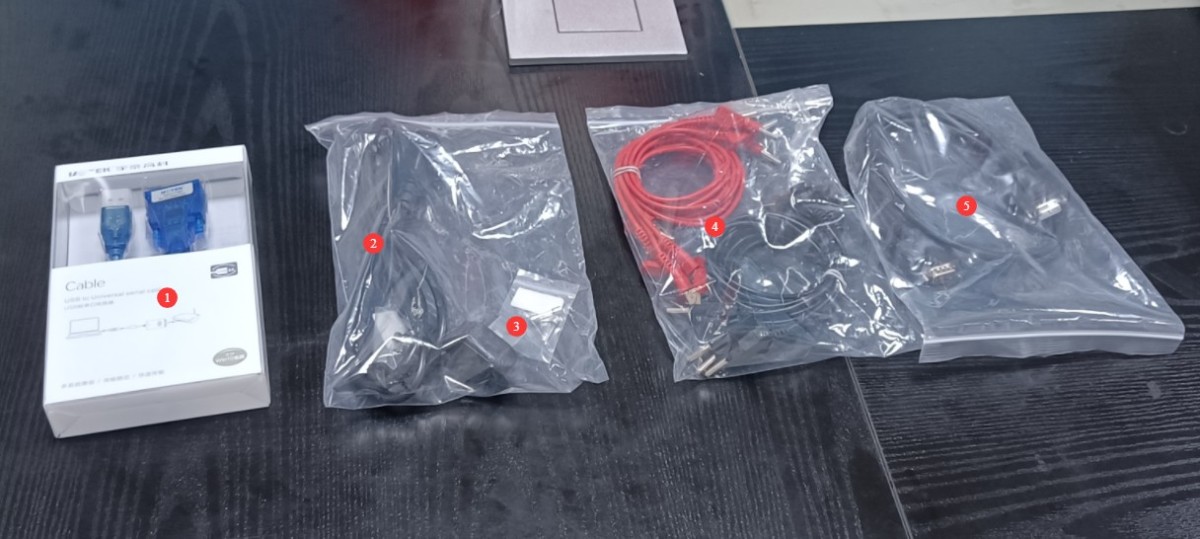
그림 1-1
1.2.3 전자 문서 다운로드
We have already sent download links for the electronic user manual, software, calibration certificate, warranty card, and other items via email at the time of shipment. Please download them promptly. If you have not received the email, please contact us to request the download links again.
2. 안전상의 주의
2.1 전기 안전
Before connecting the power cord, verify that the supply voltage is AC 220V ±10% and the frequency is 50 Hz or 60 Hz. You must use a three-prong outlet with a protective ground, and the protective ground resistance must be ≤4 Ω. Never cut or disconnect the protective ground wire, as doing so poses a risk of electric shock.
2.2 환경 안전
Do not use in environments with flammable or explosive materials, strong electromagnetic interference, high temperatures and humidity, or excessive dust levels. Operating environment: Temperature 5°C to 35°C, relative humidity ≤ 65% RH.
2.3 운영 절차
Before connecting the wires, the power supply to the sample load must be disconnected; do not connect wires while the circuit is energized. Connect voltage leads in parallel and current leads in series; under no circumstances should a current circuit be connected to a voltage terminal or a voltage circuit to a current terminal. Pay attention to the positive and negative polarities when performing DC measurements. After connecting the wires, tighten the terminals and ensure that no bare wires are exposed to prevent short circuits or electric shock.
When measuring high-frequency signals, keep the wiring as short as possible and use thick, multi-strand wire; route the wiring away from the metal casing of the equipment to minimize interference from distributed capacitance.
3. 장비 작동
3.1 전면 패널 소개
See Figure 3-1. Note: Using the desktop software makes operation more convenient and eliminates the need to use the front panel of the device; if you need to print a test report, you must also do so through the software. If you use the software, you only need to operate the power switch and load switch on the front panel.
| 번호 | 주의 사항 |
| ① | Input Parameter Display |
| ② | Output Parameter Display |
| ③ | Equipment Power Switch |
| ④ | Load Power Switch: Turns the load power on or off |
| ⑤ | Peak Lamp Current “Range” Button: Selects the current range when starting the test |
| ⑥ | Press the “Harmonics” key to select the function: Press this key to initiate the harmonic analysis; the analysis takes approximately 1 second. Once the analysis is complete, the total voltage harmonics are displayed in the voltage window, the total current harmonics in the current window, the THD (abbreviation for Total Harmonic Distortion) in the power window, and the SPEC (harmonic indicator) in the “Power/Order” window. Press the “Harmonics” key again to exit the harmonic analysis. |
| ⑦ | On the Harmonic Analysis screen, press the “▲” or “▼” keys to display the voltage and current harmonic components from the 0th to the 50th order. |
| ⑧ | Input Function: Select the “Wideband” button: Press this button to select the frequency response—narrowband or wideband—for input characteristic testing under steady-state conditions. When the corresponding LED is lit, the setting is wideband (45 Hz–1 MHz); when the LED is off, the setting is narrowband (45 Hz–5 kHz). |
| ⑨ | To select the input function, press the “HZ/°” key: Each time you press this key, the “PF/DF” window alternates between displaying the power factor and the phase shift factor. |
| ⑩ | Press the “Start” button: Press this button to initiate the startup test; the corresponding indicator light will illuminate, and “STR-” will appear in the display window. At this point, turn off the load power switch. After allowing the unit to cool slightly, turn the load switch back on. The instrument will then begin data acquisition, and “STR-” will flash on and off in the display window. Once the test is complete, the corresponding parameters will be displayed. Once a test is complete, the instrument enters a standby state. To perform the next test, press the Start button again. To exit the startup test, press the Steady-State button. |
| ⑪ | Press the “Average” button. When this button is pressed, the startup test interface will display the average startup current and startup energy efficiency in the “Peak Ratio/Average/Energy Efficiency Index/Ripple” window. |
| ⑫ | Steady-State “Test” Button: After the instrument powers on, it automatically enters steady-state testing; when the instrument is in the startup test mode, pressing this button returns it to steady-state testing. |
| ⑬ | Steady-State “Average” Button: Press this button to illuminate the “Average” indicator in the current display window. At this point, the current value shown in this window represents the average current of the lamp. |
| ⑭ | Steady-state “Ripple” button: Press this button to display the ripple current (A/mA indicator lit) and the energy efficiency coefficient (% indicator lit) in the energy efficiency coefficient/ripple window. |
| ⑮ | Steady-state “Latch” key: Press this key to latch the current test data for reading and analysis. Press any key again to exit the latch mode. |
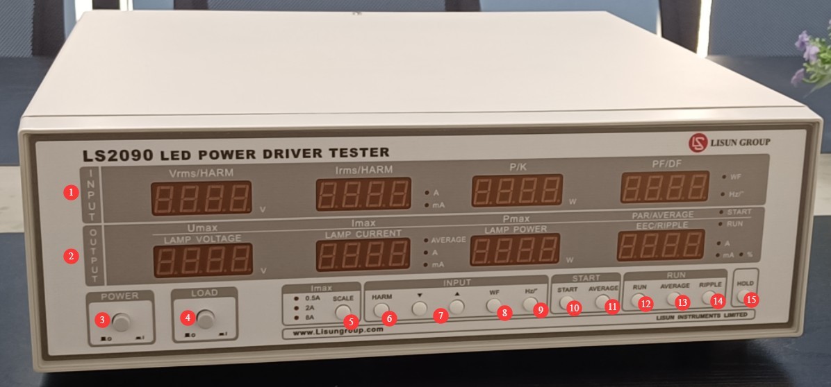
그림 3-1
3.2 Introduction to the Back Panel and Wiring
Note: To ensure safety during operation, make sure the load power switch on the front panel of the equipment is in the off (up) position before connecting the wires.
3.2.1 Using LED Light Sources
| 번호 | 주의 사항 |
| ① | Power cord jack, for connecting the device to an appropriate power source |
| ② | Equipment Input Power Supply Fuse |
| ③ | Protective grounding terminal: Internally short-circuited to the grounding terminal of the power cord. If the power cord already provides adequate protective grounding, this terminal does not need to be connected. |
| ④ | Load Input Power Supply Fuse |
| ⑤ | RS-232 communication cable, connected to a computer, or connected to a computer via an RS-232-to-USB adapter cable |
| ⑥ | V voltage terminal: Connect the load’s input power supply cable to this terminal and connect it to the LISUN LSP Series AC power supply or another suitable power source. |
| ⑦ | Use a jumper wire to short-circuit the two black terminals at the V and A terminals. |
| ⑧ | Connect the two red terminals on the V and A terminals to the input of the LED driver. |
| ⑨ | Connect the red and black terminals of the DUT to the output terminals of the LED driver, observing the polarity: red is positive and black is negative. |
| ⑩ | Connect the blue and yellow terminals of the LED LOAD to the LED light source. Pay attention to polarity: blue is positive and yellow is negative. |
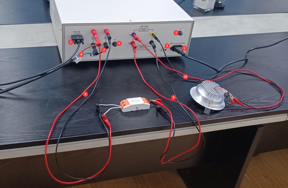
그림 3-2
3.2.2 Using the MB98 DC Electronic Load
See Figure 3-3. Connect the LED LOAD to the MB98 series electronic load, observing the correct polarity. All other connections are the same as in Section 3.2.1.
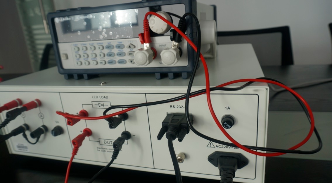
그림 3-3
3.3 Equipment Testing Procedures
3.3.1 Using LED Light Sources
| 명령 | 주의 사항 |
| ① | Follow the wiring instructions in Section 3.2.1. |
| ② | Powering On the Equipment |
| ③ | Based on the LED driver input parameters (such as input voltage and frequency), configure the LISUN LSP Series AC power supply (or other power supply) and start the output. |
| ④ | Press the power switch on the front panel of the device. The LED driver power supply turns on, and the LED light comes on. |
| ⑤ | See Section 3.1 for test parameters . Note: When starting the test, turn off the load power supply; wait until the sample has cooled down before turning the load power supply back on. The equipment will automatically run the startup parameters. |
| ⑥ | Press the load power switch again to snap it back up. The LED driver power supply is turned off, and the LED light goes out. |
| ⑦ | 전원 끄기 LISUN LSP Series AC power supply (or other power supply) output |
| ⑧ | Replace the sample for testing, or shut down the equipment |
3.3.2 Using the MB98 DC Electronic Load
| 명령 | 주의 사항 |
| ① | Follow the wiring instructions in Section 3.2.2. |
| ② | Turn on the equipment; turn on the electronic load. |
| ③ | Based on the LED driver’s output parameters (voltage, current), configure the electronic load (you need to set either the voltage or current; using voltage as an example, press V-SET twice to set the voltage, then press ENT to confirm), and then press ON/OFF to start the output. |
| ④ | Based on the LED driver’s input parameters (such as input voltage and frequency), configure the LISUN LSP Series AC power supply (or other power supply) and start the output. |
| ⑤ | Press the load power switch on the front panel of the device. The LED driver power supply turns on, and the electronic load displays the current voltage and current values of the LED driver output. |
| ⑥ | See Section 3.1 for test parameters . Note: When starting the test, turn off the load power supply; once the sample has cooled, turn the load power supply back on, and the equipment will automatically initiate the test. |
| ⑦ | Press the load power switch again to make it spring back. The LED driver power supply is turned off. |
| ⑧ | 전원 끄기 LISUN LSP Series AC power supply (or other power supply) output |
| ⑨ | Press the ON/OFF switch on the electronic load to turn off the output. |
| ⑩ | Replace the sample for testing, or turn off the equipment and electronic load. |
4. Software Operation (Using the LS2090-IEC Software as an Example)
4.1 소프트웨어 설치
Software System Requirements: Computers running Windows 7 or later.
The LS2090 connects to the computer via an RS-232 cable. If the computer does not have an RS-232 port, you will need to use an RS-232-to-USB adapter cable to connect the two devices.
See Figure 4-1 for the software installation package.
| 번호 | 주의 사항 |
| ① | LS2090 software—please double-click to install |
| ② | RS-232-to-USB Adapter Driver: If you are using an RS-232-to-USB adapter, please double-click to install it. |

그림 4-1
4.2 소프트웨어 개요
4.2.1 Software Start Screen
그림 4-2를 참조하세요.
| 번호 | 주의 사항 |
| ① | File: New, Open, Save, Save As, Print, Print Preview, Exit |
| ② | Settings: System Configuration, Product Information |
| ③ | Testing: Input Characteristic Testing, Output Characteristic Testing, Start-up Characteristic Testing, Input/Output Testing, Start-up Input/Output Testing |
| ④ | View: View the IEC 61000-3-2 report, view input characteristics, view harmonic content, view output characteristics, view startup characteristics, view input and output, wideband |
| ⑤ | Help: Software Version Information, Switch Between Chinese and English |
| ⑥ | New: Create a new blank test file in .lpdx format |
| ⑦ | Open: Open a saved test file in .lpdx format |
| ⑧ | Save: Save the test file in .lpdx format |
| ⑨ | Print Test Report |
| ⑩ | 제품 정보 |
| ⑪ | Clear: Clear the data from the Excel list |
| ⑫ | Add: Add the current test data (excluding waveform data) to the Excel list. |
| ⑬ | Export: Exports all test data added to the Excel list so you can view it in Excel. |
| ⑭ | 시스템 구성 |
| ⑮ | Wideband (press to select wideband; release to select narrowband): In steady-state conditions, you can select either the narrowband (45 Hz–5 kHz) or wideband (45 Hz–1 MHz) frequency response for input characteristic testing. |
| ⑯ | Switch the display units for total harmonic current: Permitted harmonic current in A/per watt; Permitted harmonic current in mA/W |
| ⑰ | Input Characteristics Testing |
| ⑱ | Output Characteristics Testing |
| ⑲ | Launch Feature Testing |
| ⑳ | 입력/출력 테스트 |
| ㉑ | Start Input/Output Testing |
| ㉒ | Continuous Testing: Continuous Testing of Input Characteristics, Continuous Testing of Output Characteristics, Continuous Testing of Input and Output |
| ㉓ | Stop Test: While in continuous test mode, click to stop the test |
| ㉔ | View the IEC 61000-3-2 Report |
| ㉕ | View Input Characteristics |
| ㉖ | View Harmonic Content |
| ㉗ | View Output Characteristics |
| ㉘ | View Input and Output |
| ㉙ | View Startup Features |
| ㉚ | 소프트웨어 버전 정보 |
| ㉛ | Harmonic Limitation Standards: For example, if your load consists of LED lighting fixtures, select Class C. |
| ㉜ | Five harmonic limitation standards are used to evaluate total current distortion (THD) and voltage harmonic content. Note: For devices rated at ≤25 W, there are three evaluation criteria; meeting any one of them is sufficient. |
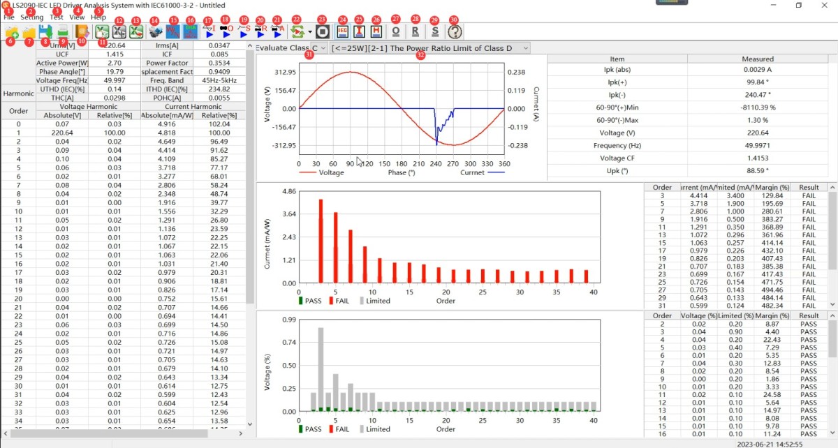
그림 4-2
4.2.2 System Configuration Interface
그림 4-3를 참조하세요.
| 번호 | 주의 사항 |
| ① | Baud rate: 115200 by default; no changes needed |
| ② | Select “Auto Detect,” and the software will automatically detect the communication port. If detection fails, please check the communication cable connection and ensure the driver is installed. |
| ③ | Is the unit for the absolute value of harmonic current mA/W? |
| ④ | Total Harmonic Distortion Calculation Method: IEC (default) or CSA |
| ⑤ | Phase Shift Factor Definition: COSφ (default) or IEC |
| ⑥ | "확인"을 클릭하여 저장합니다. |
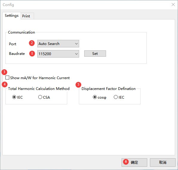
그림 4-3
4.2.3 Product Information Screen
그림 4-4를 참조하세요.
| 번호 | 주의 사항 |
| ① | Enter reports, products, and test information |
| ② | Enter the sample’s rated voltage and rated frequency correctly. |
| ③ | Reports, Auto-Increment Function for Product Numbers |
| ④ | "확인"을 클릭하여 저장합니다. |
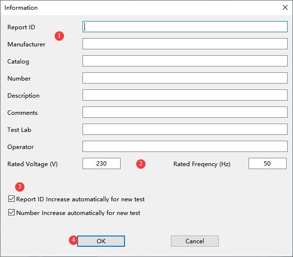
그림 4-4
4.3 Software Testing Procedures
| 명령 | 주의 사항 |
| ① | Follow the wiring instructions in Section 3.2. |
| ② | Powering On the Equipment |
| ③ | Operate the equipment as described in Section 3.3. |
| ④ | Refer to Section 4.2.2 to verify that software communication is functioning properly, and configure settings as needed. |
| ⑤ | Refer to Section 4.2.3 to correctly enter LED driver product information |
| ⑥ | Refer to Section 4.2.1 for instructions on conducting tests, viewing test information, exporting test files, and printing test reports via the software interface. Note : When starting a test, follow the software prompts to turn off the load power supply on the front panel of the device; wait until the sample has cooled before turning the load power supply back on. The software will automatically set the test startup parameters. |
5. 장비의 일상 유지보수 및 관리
5.1 일상적인 유지보수
5.1.1 일일 청소
Be sure to turn off the power and unplug the power cord before cleaning. We recommend wiping the unit with a soft, antistatic cotton cloth and a mild detergent; do not spray liquids directly onto the unit. Do not use chemical solvents such as benzene, toluene, or acetone.
5.1.2 정기 검사
Before each use, check the power cord and terminal connections to ensure there are no loose connections or signs of burn damage; after turning on the unit, verify that the indicator lights and display are functioning properly.
5.2 Storage Specifications
5.2.1 저장 환경 요구 사항
Temperature: 5°C to 35°C; relative humidity: ≤65% RH; dry, dust-free environment free of corrosive gases.
5.2.2 장기 저장 작업
Turn off the power and unplug all cables; clean the equipment and wrap it in dust-proof film; power it on for 30 minutes each month to prevent moisture damage to the components.
5.3 교정 주기 요구사항
측정 정확도와 장비의 작동 신뢰성을 보장하기 위해, 자격을 갖춘 제3자 계측 연구소에 정기적으로 보내 교정을 받는 것이 좋습니다. 권장 교정 주기는 12개월입니다. 사용자는 사용 빈도, 환경 조건 및 품질 시스템 요구 사항을 고려하여 구체적인 교정 주기를 결정할 수 있습니다.
6. 문제 해결 및 일반적인 문제 해결 방법
| 결함 증상 | 가능한 원인들 | 순서 |
| 전원이 켜지지 않음 | Loose input power supply cord, blown fuse | Turn off the power and check the connection of the input power supply cord; turn off the power, troubleshoot for short circuits or overloads, replace the fuse with one of the same rating, and do not increase the current rating. |
| The load still does not respond after the load power switch is turned on | Incorrect wiring polarity for the DUT or LED LOAD | Follow the troubleshooting steps in Section 3.2. Be sure to observe the correct polarity when connecting the DUT and LED LOAD terminals; failure to do so may affect load operation or even damage the equipment. |
| 통신 실패 | Communication cable connection error / Driver not installed, baud rate mismatch | See Section 3.2 for troubleshooting wiring; see Section 4.1 for troubleshooting driver installation; see Section 4.2.2 for troubleshooting settings. |
| The data shown has not changed. | Latch Function Triggered | Refer to Section 3.1 to check and disable the latch function. |
7. 포장 목록
| 그렇지 않습니다. | 이름 | 수량 |
| ① | LS2090 LED Driver Comprehensive Performance Tester | 1 부 |
| ② | RS-232-USB 어댑터 케이블 | 1 조각 |
| ③ | 전원 코드 | |
| ④ | 예비 퓨즈 | 2 |
| ⑤ | Red and Black Test Leads | 5 세트 |
| ⑥ | RS-232 통신 케이블 | 1 조각 |