
 영어
영어 中文简体
中文简体 Русский
 Español
 Português
 Türkçe
 العربية
 Deutsch
 Polski
 Italiano
 Français
 한국어
한국어 ไทย
ไทย Tiếng Việt
 日本語
日本語





























자동 전기 안전 시험기
사용자 설명서
적용 할 수있는 LISUN 모델: LS9955,LS9956
1. 제품 개봉 및 기본 사용법 익히기
1.1 주요 기술 사양
| AC and DC Withstand Voltage Testing | 절연 저항 시험 (IR) | ||||
| 전압 범위 | 정확성 | 전류 범위 | 절연 저항 범위 | 정확성 | 전압 범위 |
| 100 ~ 4000V | ± 3의 % | AC: 0.10–20.00 mA | 1.00–2000 MΩ | ± 3의 % | 직류 100~1000V |
| DC: 0.10–12.00 mA | |||||
| 누설 전류 테스트 (LLC) | Ground Resistance Test (GR) | ||||
| 누설 전류 범위 | 정확성 | 전압 범위 | 접지 저항 범위 | 정확성 | 출력 전류 |
| 0.10–20mA | ± 0.3의 % | 교류 10.0~300.0V | 0~600mΩ | ± 3의 % | AC 1.00–30.00 A |
| Power Test (POWER) (Note: The LS9955 does not include this feature) | |||||
| 전압 | Current | 출력 | 역률 | 정확성 | 시험 시간 |
| 10 ~ 300V | 0.010–20.00A | 1.0–6000.0W | 0.2-1.0 | 클래스 0.5 | 0~999.9초 |
1.2 개봉 및 내용물 확인
1.2.1 포장 해제 및 육안 검사
기기를 개봉할 때는 날카로운 도구로 케이스에 흠집이 나지 않도록 조심스럽게 다루십시오. 개봉 후에는 먼저 기기 외관을 검사하여 눈에 띄는 변형이나 찌그러짐이 없는지, 버튼이 손상되었거나 헐거워지지 않았는지 확인하십시오. 기기 또는 부속품에 이상이 발견되면 전원을 켜지 마시고 즉시 저희에게 연락해 주십시오.
1.2.2 호스트 및 액세서리
호스트: 1 LS9955/LS9956 숙주.
The main components are as follows:
| 번호 | 주의 사항 |
| ① Power cord | |
| ② Test Kit | Power cord used to connect the device to the power source of the device under test |
| ③ Grounding Clamp | Used to connect the equipment to the grounded enclosure of the device under test |
| ④ Communication Cable | (If the software supports this feature) Used to connect the device to a computer. Note: Do not use this cable interchangeably with other RS-232 communication cables. |
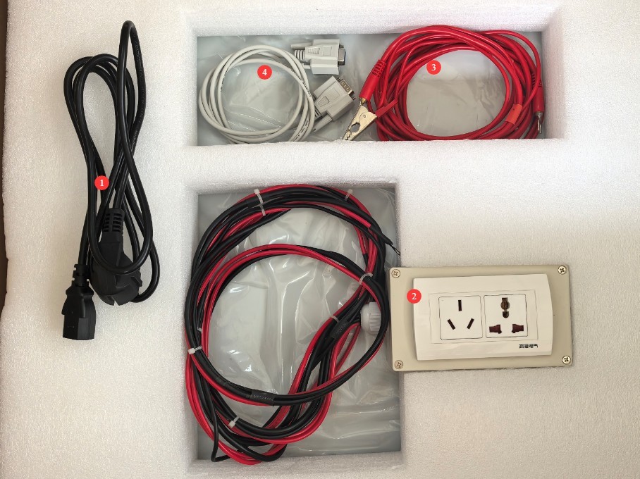
그림 1
Download links for the electronic user manual, software, warranty card, and other materials have been sent via email. Please download them promptly. If you missed the email, you may contact us to request the download links again.
2 안전주의 사항
2.1 전기 안전
2.1.1 전원 요구 사항
Use a single-phase AC 220V ±10%, 50/60 Hz three-prong outlet; the ground prong must be connected to ground.
2.1.2 접지 요구 사항
The instrument ground wire is reliably connected to the protective ground wire, and the protective ground resistance is ≤4 Ω.
2.2 환경 안전
2.2.1 Temperature and Humidity Requirements
Avoid using the device in environments where humidity exceeds 70% (without condensation) or where the temperature is outside the range of 0–35°C. The optimal operating temperature is 25±2°C.
2.2.2 Environmental Contraindications
Environments with strong magnetic fields and strong electric fields;
Environments containing corrosive gases or liquids;
Areas with flammable and explosive dust, and areas containing hazardous materials;
Environments with heavy dust, high temperatures and humidity, and direct sunlight.
2.3 작동 안전
During testing, the casing of the test object is electrically charged; do not touch it with your bare hands under any circumstances;
The test specimen must be placed on a rubber insulating mat;
Operators must wear rubber insulated gloves;
Operators must have dry hands and must not wear any metal jewelry; eating or drinking is prohibited during testing to prevent accidents caused by electric shock;
Before replacing the test object, you must first stop the test and disconnect the test object from the input power supply;
여러 사람이 참여하는 경우, 역할과 책임을 명확하게 정의하고 오류를 방지하기 위해 테스트 시작 전에 서로 확인해야 합니다.
2.4 기타
본 설명서에 나와 있지 않은 사항에 대해서는 주의를 기울여 진행하시거나 당사에 문의해 주십시오.
3. 안전성 테스트 절차
3.1 Standard Test Parameters (Reference: GB/T 7000.1-2023)
| 시험 항목 | 관련 표준 조항 | 테스트 매개변수 설정 | 허용 한계 | 시험 시간 |
| 접지 저항 시험 | 7 | Test Current: 25A | ≤0.1Ω | 5s |
| 절연 저항 테스트 | 10.2 | Test Voltage: 500 V DC | 2MΩ 이상 | 60s |
| Dielectric Strength (Withstand Voltage) Test | Test Voltage: 1500 V AC | No breakdown, no flashover; leakage current ≤ 5 mA | ||
| 누설 전류 테스트 | 10.3 | Test voltage: 1.06 × rated voltage | ≤0.25 mA (standard products) | 10 seconds per phase, automatic phase switching |
Note: This manual uses GB/T 7000.1-2023 as an example only. If you are referring to other standards, please consult the corresponding standard for the correct test parameters.
3.2 장비 배선
3.2.1 Introduction to the Back Panel and Wiring
| 번호 | 주의 사항 |
| ① ② | Connect the device under test to its rated input power supply. For example, if the device under test is rated for 220 V, connect it to a 220 V regulated power supply. Note: The LS9956 is used to measure the power of the device under test; the LS9955 does not have this function and therefore does not need to be connected. |
| ③④ | Leakage current test voltage input. Note: Refer to Section 4.1; a voltage of 1.06 times the rated voltage must be applied for testing. For example, if the rated voltage of the device under test is 220 V, a 234 V regulated power supply must be used for the leakage current test. |
| ⑤ | Low-voltage startup test. The standard versions of the LS9955 LS9956 do not have this feature; no connection is required. |
| ⑥⑦⑧⑨ | Connect the test box to the terminal block: terminals ⑥ and ⑦ are connected to the two red power wires from the test box, while terminals ⑧ and ⑨ are connected according to their respective shapes. |
| ⑩⑪ | Connect the ground clamp to the terminals, distinguishing between them based on their shape. Note: If the device under test does not have a ground wire, the ground clamp must also be connected to terminals ⑧ and ⑨, rather than terminals ⑩ and ⑪. |
| ⑫ | RS-232 communication port; if no software functions are required, there is no need to connect it. |
| ⑬ | 전원 코드 |
| ⑭ | Test Input Power Supply Circuit Breaker |
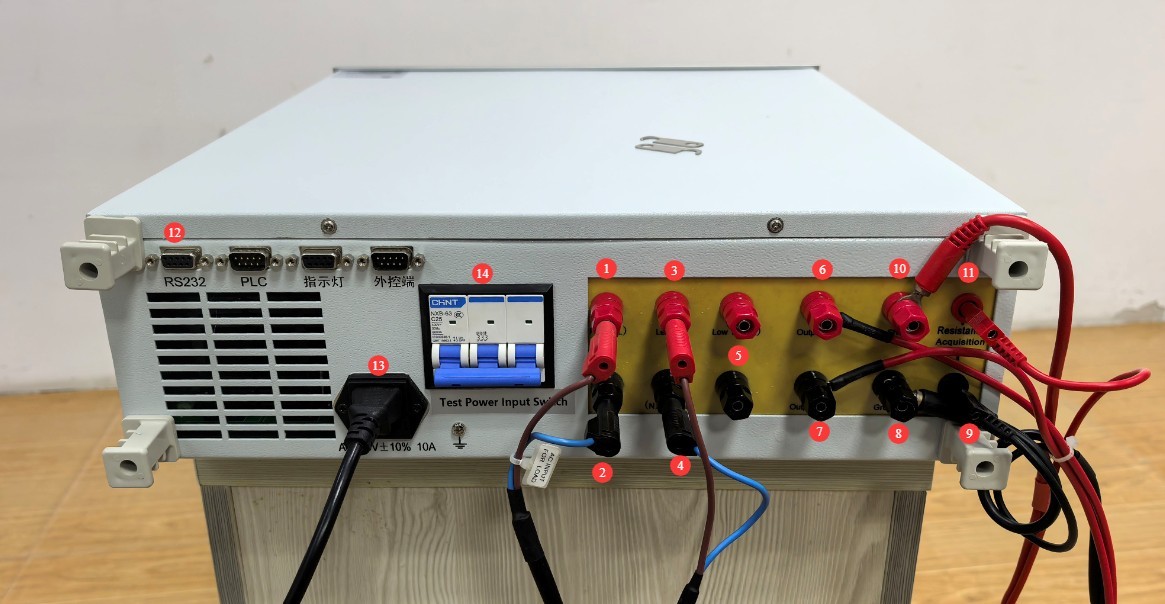
그림 2
3.2.2 Connecting the Test Object
The test object’s casing must be clean and free of oil; place it in the center of the insulating mat, away from the metal work surface.
| 번호 | 주의 사항 |
| ① | Connect the power cord of the device under test to the test kit. |
| ② | The grounding clamps must be attached to a metal part of the test object’s housing to measure ground resistance and withstand voltage. Note: If the test object has a ground wire, ensure that the metal part of the housing where the grounding clamps are attached is electrically connected to the test object’s ground wire. If there is no connection or the resistance is too high, when the earth clamps are used to test ground resistance, the device will display an “Open” message or indicate a test failure, meaning the device has failed the test; if the device does not have a ground wire, the earth clamps can be attached directly to the device’s housing and used solely for dielectric strength testing. |
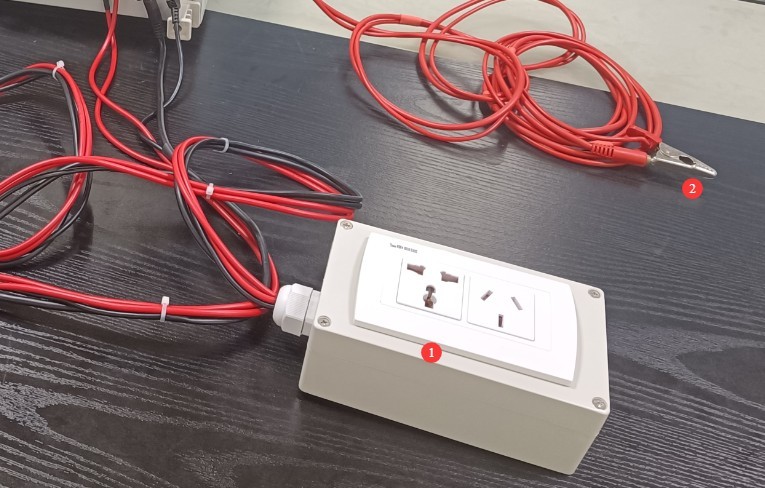
그림 3
After all connections have been made and verified, turn on the circuit breaker on the back of the device.
3.3 전면 패널 작동
장치를 켜십시오.
| 번호 | 주의 사항 |
| ① | Use the left and right arrow keys to move the cursor |
| ② | The device can store a total of 199 sets of test data. First, move the cursor to the group number field and use the numeric keys to modify the group number. Note: You can overwrite data by using the same group number, or create a new test group using a different group number. |
| ③ | Continue moving the cursor to use the up and down arrow keys to modify the test items, and the number keys to modify the test parameters. Note: If the test object does not have a ground wire, there is no need to test the ground resistance; set this item to NULL. |
| ④ | Click “Save” to save the test parameters to the corresponding group number. The next time you run a test and need the same parameter settings, you can simply switch the test group number to the one you saved previously to retrieve them directly. |
| ⑤ | Once everything is set up, move the cursor to the page number. |
| ⑥ | Press the green Start button, and the device will automatically perform tests according to the configured test items, sequence, and parameters. |
| ⑦ | If you need to stop the test during the testing process, press the Stop button. |
| ⑧ | Status Indicator: During Testing, Test Passed, Alarm/Test Failed |
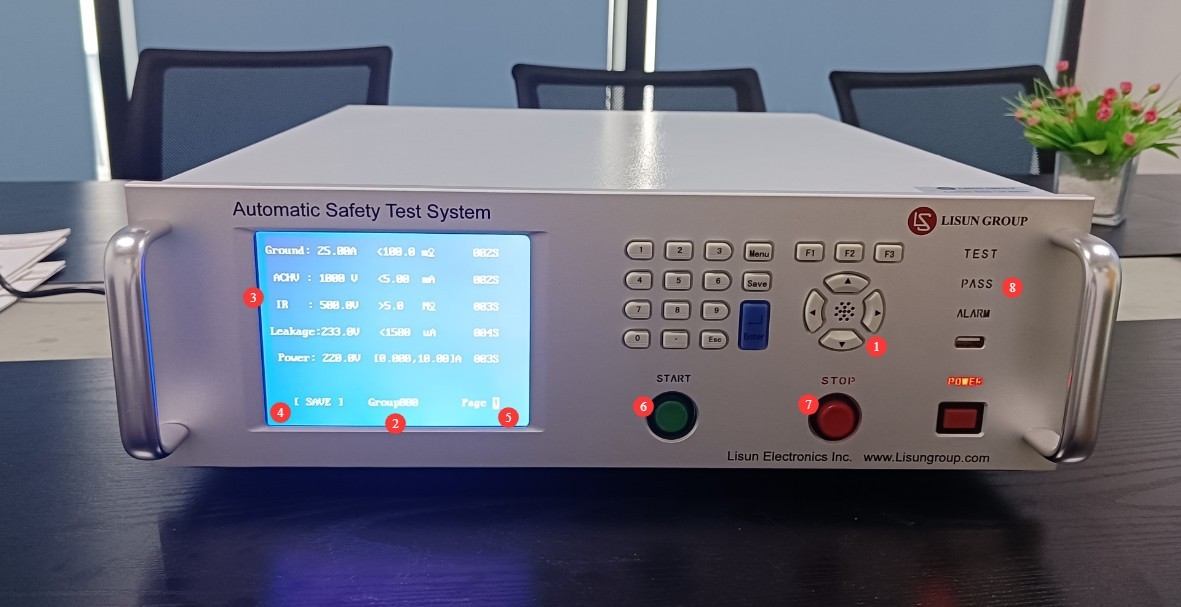
그림 4
Note 1: For leakage current testing, the test voltage must be set to 234 V (using a 220 V test object as an example), i.e., it must match the leakage current test voltage of the connected device.
Note 2: For the LS9956 power test, the test voltage must be set to 220 V (using a 220 V device under test as an example), i.e., it must match the rated power supply of the connected device under test.
3.4 Common Equipment Alarms
3.4.1NG
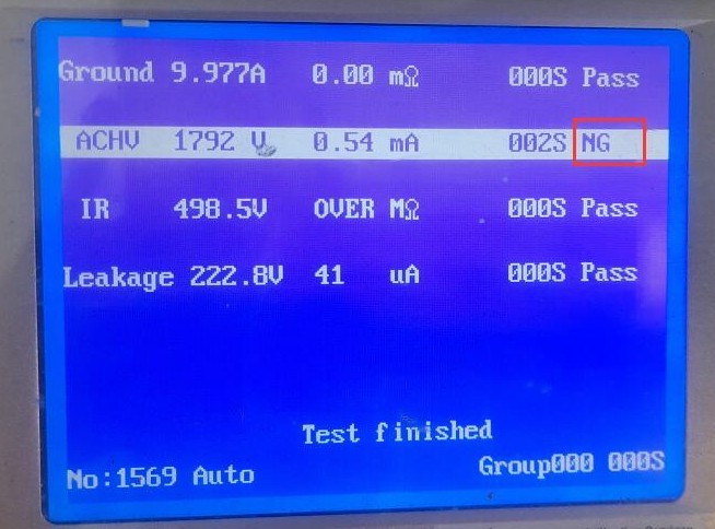
그림 5
Failed the test.
3.4.2 OVER
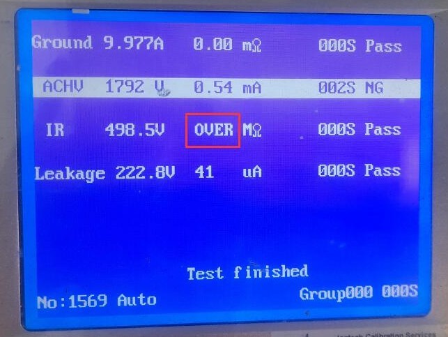
그림 6
If the insulation resistance test value exceeds the equipment’s upper measurement limit (2000 MΩ), the test is considered passed.
3.4.3 조정
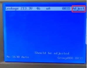
그림 7
The leakage current test voltage input does not match the leakage current test voltage setting. Refer to sections 4.2.1 and 4.3 for adjustments.
3.4.4 Exceed current break
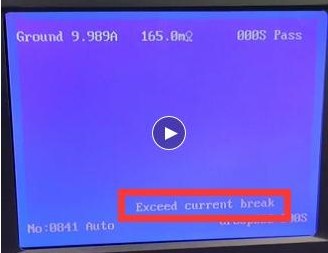
그림 8
The current exceeds the equipment’s limit. Please check for a short circuit between the live wire, neutral wire, and ground wire of the device under test.
3.4.5 열기
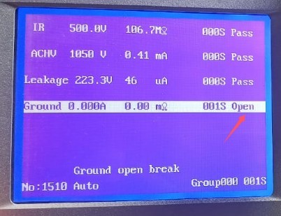
그림 9
During the ground resistance test, an open-circuit error is displayed. Refer to Section 4.2.2 for adjustments.
3.5 테스트 종료
3.5.1 Shutdown Procedure
Wait for the test to finish or press STOP to stop the test → Turn off the circuit breaker on the back panel → Shut down the unit.
3.5.2 Replacing the Test Object
Wait for the test to finish or press STOP to stop the test → Turn off the circuit breaker on the back panel → Replace the test object → Turn on the circuit breaker on the back panel → Set the parameters and run the test.
4. 소프트웨어 사용
4.1 Hardware Wiring Adjustments
4.1.1 Connecting the Communication Cables
1.2.2를 참조하십시오.
4.1.2 Connecting the Test Power Supply
구매하셨다면 LISUN power supply and your device model is LS9956.
| 번호 | 주의 사항 |
| ① | 에 연결 LISUN power supply output |
| ② | Use the shorting cable provided with the LISUN device to short-circuit the rated power input terminal of the device under test to the leakage current test voltage input terminal. During the test, the LS9956 software automatically controls the power supply output to ensure that the power test and leakage current test are performed correctly. |
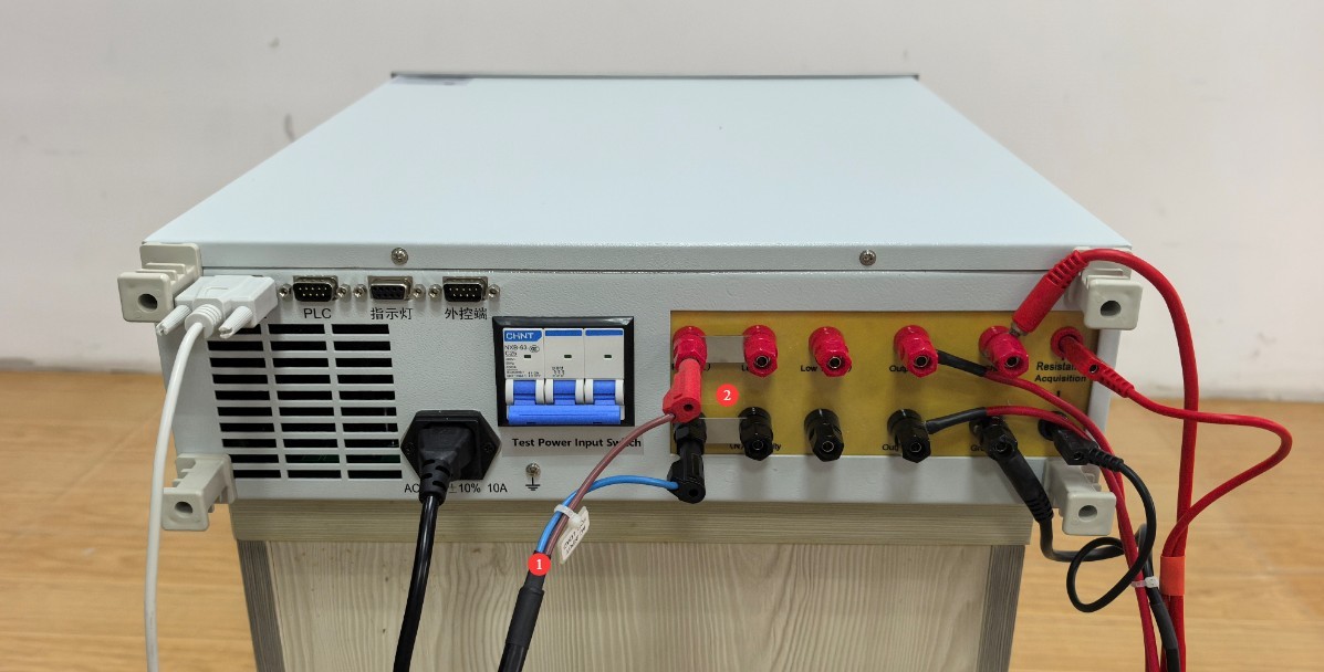
그림 10
4.1.3 Connecting the Communication Cables
당신이 있다면 LISUN power supply, connect the LS9955/LS9956 communication cable and the LISUN power supply communication cable to the RS232 communication box, and then connect the communication box to your computer.
당신이 LISUN power supply, connect the LS9955/LS9956 communication cable to the RS232-to-USB adapter and then connect it to your computer.
Note: If your computer has enough RS232 ports, you do not need to use a communication box or a USB adapter cable.
4.2 소프트웨어 및 드라이버 설치
| 번호 | 주의 사항 |
| ① | LS9955/LS9956 Software: Double-click to install |
| ② | RS232 Communication Module Driver |
| ③ | RS232-USB Cable Driver |

그림 11
를 설치 RS232 Communication Box Driver.
| 번호 | 주의 사항 |
| ① | Double-click it, then follow the on-screen instructions to install it. |
| ② | Please read the instructions on how to change the port. |
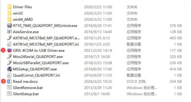
그림 12
RS232-USB adapter cable driver—please double-click to install.
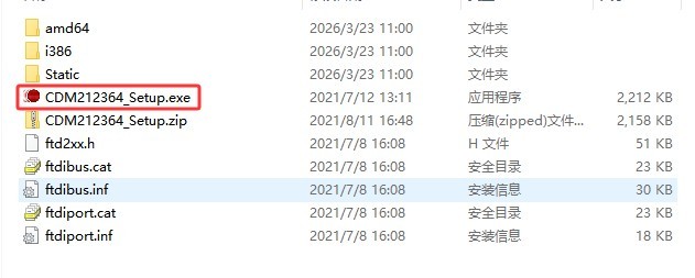
그림 13
4.3 소프트웨어 설정
4.3.1 통신 포트 설정
Click to open the port settings screen.
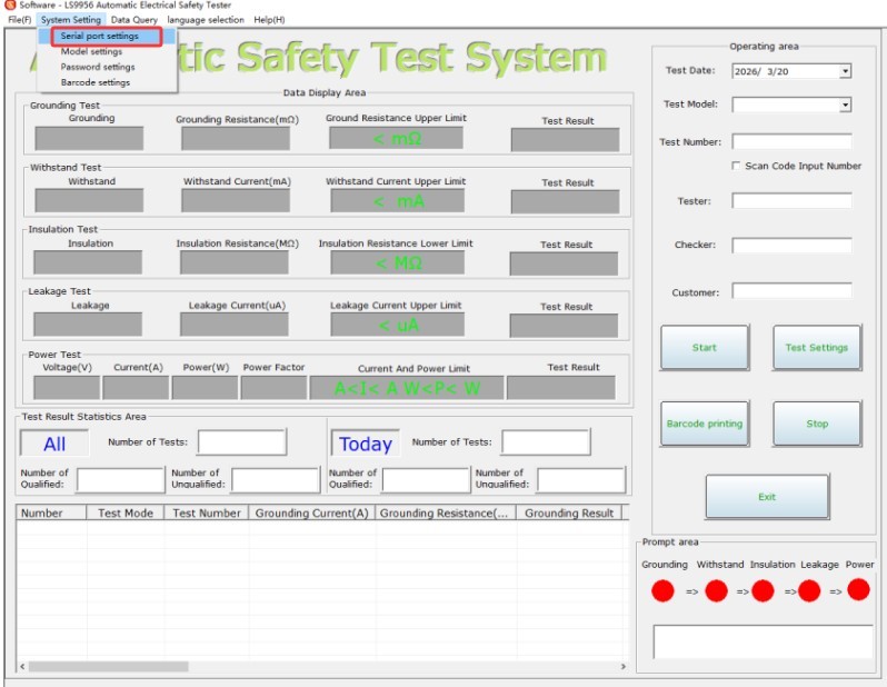
그림 14
| 번호 | 주의 사항 |
| ① | 당신이 있다면 LISUN power supply, please check the box; if you do not have a LISUN power supply, please do not check the box. |
| ② | Click “Auto Search” to automatically detect the correct communication port for the LS9955/LS9956 LISUN power supplies. Note: The software can only recognize port numbers less than 16. If the device’s port number is greater than 16, you will need to change it manually. If you are unsure how to do this, please ask your company’s IT department for assistance or contact us. |
| ③ | You can also manually select the correct communication port. |
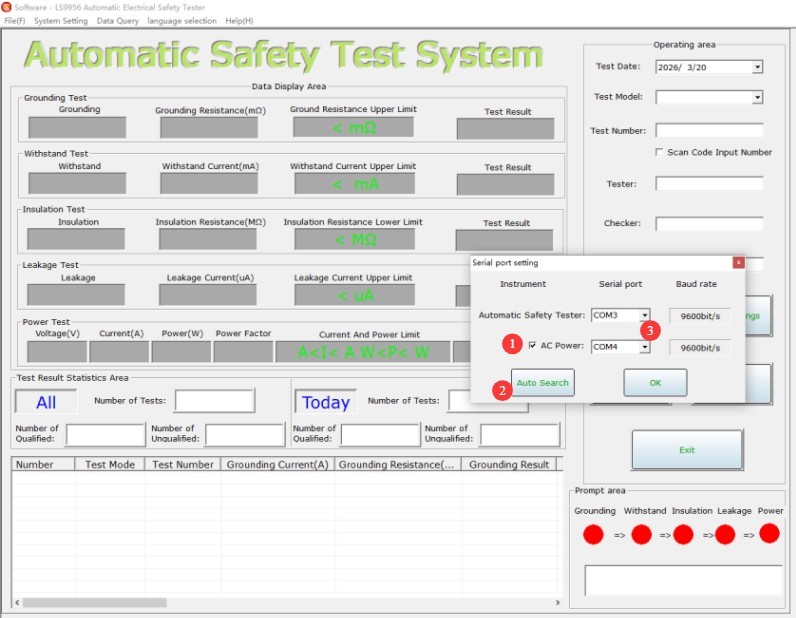
그림 15
4.3.2 테스트 매개변수 설정
테스트 매개변수 설정 화면으로 이동하세요.
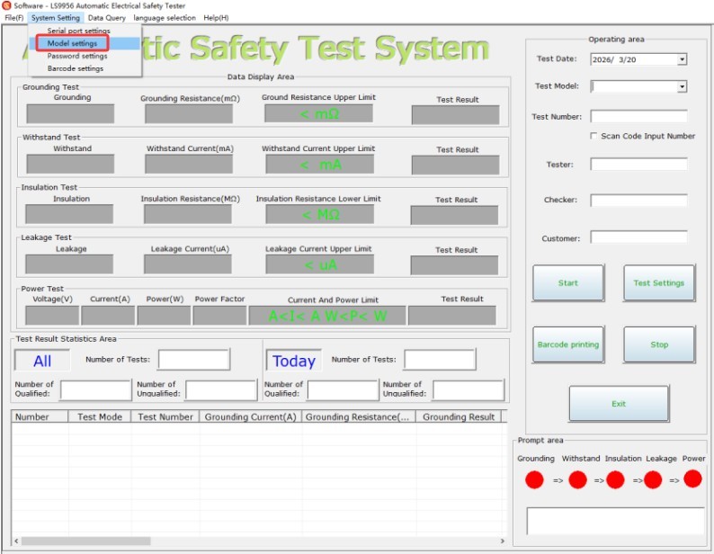
그림 16
No password is required; just click “OK” to proceed.
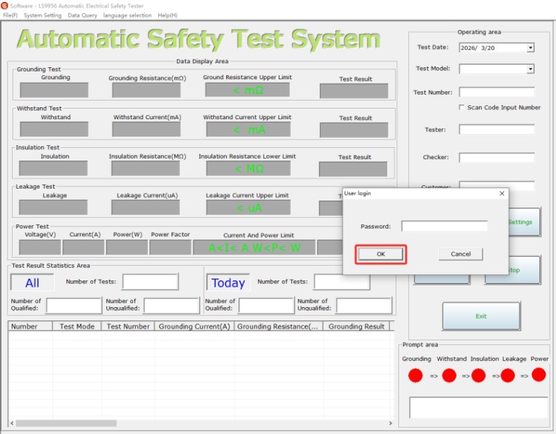
그림 17
| 번호 | 주의 사항 |
| ① | Click to change the model |
| ② | The model of the test item can be modified |
| ③ | Click to edit the limit |
| ④ | Editable Limit Groups |
| ⑤ | 제품 정보를 입력하세요 |
| ⑥ | Set the required test parameters and test sequence |
| ⑦ | Click to Save Model |
| ⑧ | Click to save the limit group |
| ⑨ | Click here to exit |
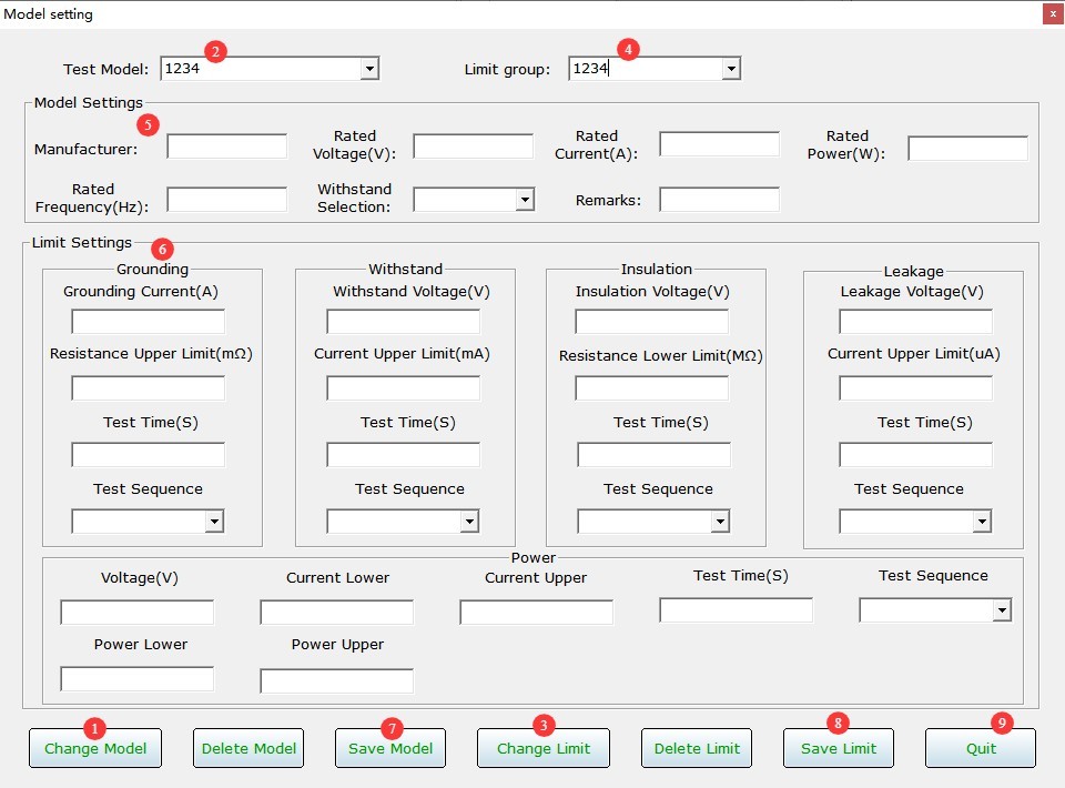
그림 18
Take the model numbers and limit value groups included with the software as an example.
| 번호 | 주의 사항 |
| ① | If a particular item does not require testing, change its test sequence to “No test.” |
| ② | The test sequences for the remaining test cases should be changed to start at 1. |
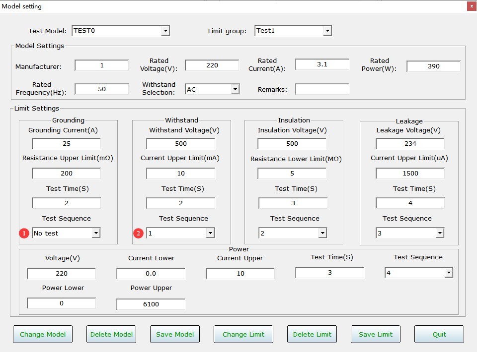
그림 19
4.4 Startup Test
4.4.1 Software Readiness
| 번호 | 주의 사항 |
| ① | Select the model you want to test |
| ② | Clicking “Start” does not instruct the device to begin testing; rather, it indicates that the software is ready and can begin recording test data at any time. |
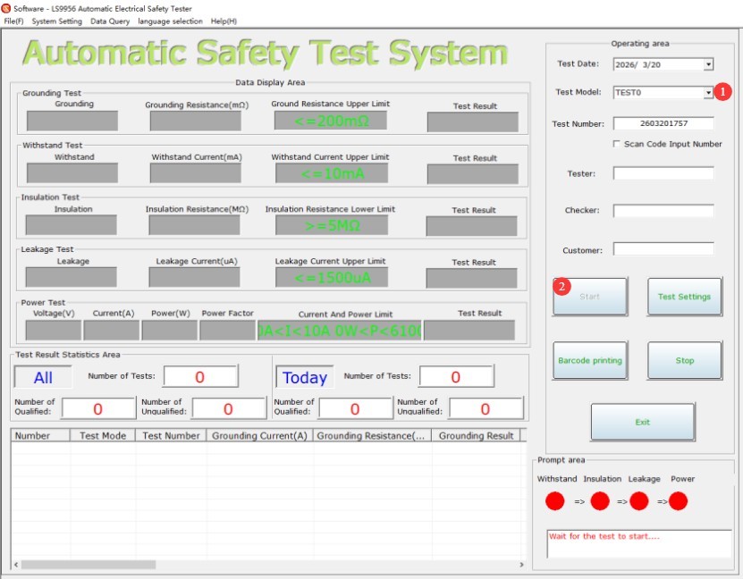
그림 20
The test items and parameters for this test model in the software are automatically synchronized to the device.
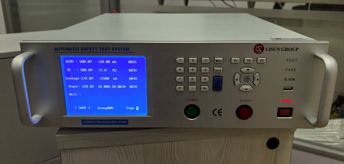
그림 21
4.4.2 Hardware Execution Testing
After verifying that all connections are correct, turn on the circuit breaker on the back of the device. Then press the Start button on the front panel to begin the test.
You can repeat the test on the device, and the software will automatically record all test data.
4.5 Test Record Management
4.5.1 Real-Time Software Test Data
| 번호 | 주의 사항 |
| ① | Both the software and hardware display the test status and progress; green indicates a passing test, while red indicates a test error or a failed test. |
| ② | All test data is saved automatically |
| ③ | Once the device has completed testing all samples, click “Stop,” and the software will stop recording data. |
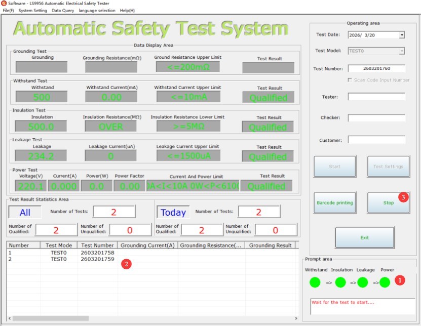
그림 22
4.5.2 View Historical Test Data
| 번호 | 주의 사항 |
| ① | Click to View Data |
| ② | You can set filter criteria |
| ③ | Click to filter all historical test data |
| ④ | You can preview, save, or print test data |
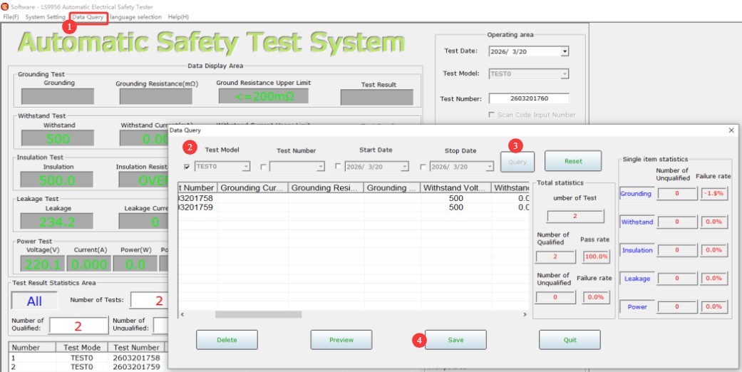
그림 23
5. 장비의 일상 유지보수 및 관리
5.1 일상적인 유지보수
Before turning on the equipment, check that the exterior is clean and free of damage, that the cables show no signs of aging or breakage, and that the connectors are secure; Check the grounding clamps for oxidation or burnout; if present, wipe them with a specialized contact cleaner, and contact us to replace parts if necessary; after testing is complete, disconnect the power and wipe the equipment surface and the test area with a dry cloth.
5.2 장기 보관
When the device is not in use for an extended period, store it in a dry, well-ventilated area, away from moisture and direct sunlight; disconnect all cables, store accessories separately, and cover the device with a dust-proof cloth; power on the device for 30 minutes each month to prevent the internal electronic components from deteriorating.
6. 문제 해결 및 일반적인 문제 해결 방법
| 결함 증상 | 가능한 원인들 | 순서 |
| 기기가 켜지지 않습니다 | 끊어진 퓨즈 | Check the fuse in the equipment’s input power supply port; if it is blown, replace it with a fuse of the same model. |
| The device did not respond after I pressed the Start button. | The screen cursor is not on the page number | Once all parameters have been set, move the cursor to the page number before starting the test. |