
 영어
영어 中文简体
中文简体 Русский
 Español
 Português
 Türkçe
 العربية
 Deutsch
 Polski
 Italiano
 Français
 한국어
한국어 ไทย
ไทย Tiếng Việt
 日本語
日本語





























오존 테스트 챔버
사용자 설명서
적용 할 수있는 LISUN 모델: OTC-150A,OTC-500A
1. 장비에 대한 기본 이해
1.1 주요 기술 사양
| LISUN 모델 | OTC-150A | OTC-500A |
| 스튜디오 크기 | 500 × 500 × 600 | 700 × 800 × 900 |
| 전원 공급 장치 | Single-phase 220–240 V, 50/60 Hz, 5 kVA | Three-phase 380 V, 50/60 Hz, 6.5 kVA |
| 오존 농도 범위 | 10~1000ppm | |
| 온도 범위 | 0 ° C ~ 60 ° C | |
| 습도 범위 | 20%–90% RH (based on 20°C–40°C) | |
| Rotational Speed of the Test Object | 8~25mm/초 | |
| Elongation of the test specimen | 5-45의 % | |
| Tensile Frequency of the Test Specimen | 분당 0~30회 | |
| Maximum elongation of the test specimen | 0~90mm(조정 가능) | |
| Tensile Test Mode for Test Specimens | A: Static stretching mode; B: Dynamic stretching mode; C: Intermittent dynamic stretching test mode | |
| 가스 유량 | 600 ± 100 mm/s (forced-air circulation mode) | |
| 제어 장치 | Proprietary Ozone Control System (7-inch Touchscreen) | |
| 노이즈 | ≤75 decibels (low-noise design) | |
1.2 개봉 및 내용물 확인
1.2.1 포장 해제 및 육안 검사
When unpacking the equipment, handle it gently to avoid scratching the exterior casing with sharp tools. After unpacking, first inspect the exterior of the main unit to ensure there are no obvious deformations, dents, or peeling paint, and that the panel instruments and buttons are not damaged or loose. If you find any damage or deformation to the device or its accessories, do not power it on. Contact LISUN after-sales personnel immediately.
1.2.2 Host Categories
Ozone Test Chamber (Main Unit): 1 unit.
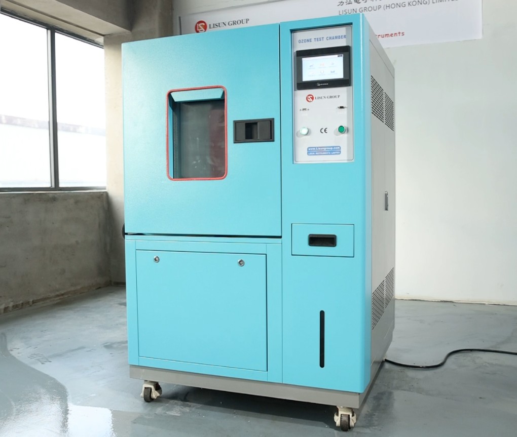
그림 1
Air compressor: 1 unit.
Note: The air compressor is an optional accessory. The ozone chamber includes an automatic exhaust function, which is used to quickly and automatically remove residual ozone from the chamber after testing is complete. To enable the automatic exhaust function, the user must install an air compressor. However, the absence of an air compressor does not affect the operation of the ozone chamber.
1.2.3 소모품 및 액세서리
After opening the test chamber door, you will find a sealed bag containing accessories in the groove along the door seal. It includes a triangular key (used to remove the panel during maintenance) and gauze (as a spare; required for the humidity sensor). The gauze should be replaced after 60 days of cumulative use or when it becomes stiff. You may contact LISUN to purchase replacement parts or purchase medical-grade non-woven gauze or high-count cotton cloth on your own.
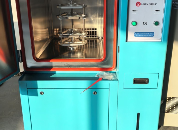
그림 2
The download links for the digital user manual, warranty card, and other documents have been sent to you via email. Please download them as soon as possible. If you missed the email, please feel free to contact us to request the download links again.
1.3 장비 구조 설명
1.3.1 시험 챔버의 정면도
① Touchscreen; ② USB and RS232 ports (the USB port is used to export test curves; the RS232 port is for backup); ③ Power and lighting switches; ④ Test chamber door; ⑤ Water-filling drawer; ⑥ Water tank level viewing window.
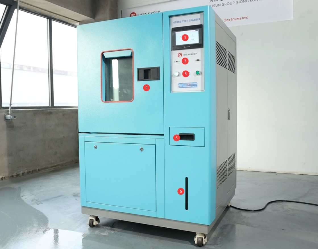
그림 3
1.3.2 시험실 후면
① Power cord; ② Drain/overflow outlet—connect a flexible hose with an inner diameter of φ12 mm to a drain or other water container; ③ Automatic water inlet—functions the same as the water-filling drawer; if connecting, use a flexible hose with an inner diameter of φ6 mm to connect to a water source with adequate water pressure;④ Circuit breaker; ⑤ Air compressor intake.
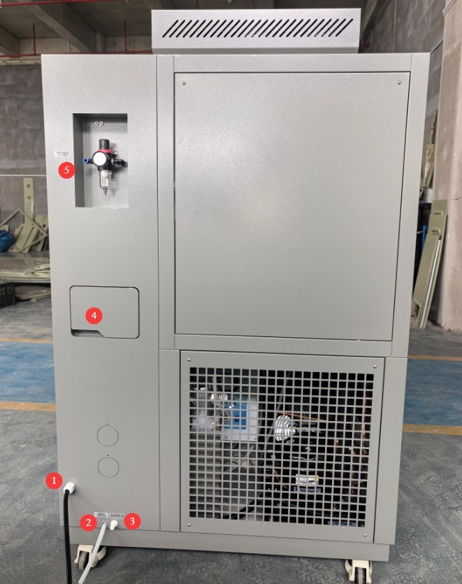
그림 4
1.3.3 Inside the Test Chamber
① Air outlet; ② Air return; ③ Temperature and humidity sensor; ④ Sample tension and rotation frame.
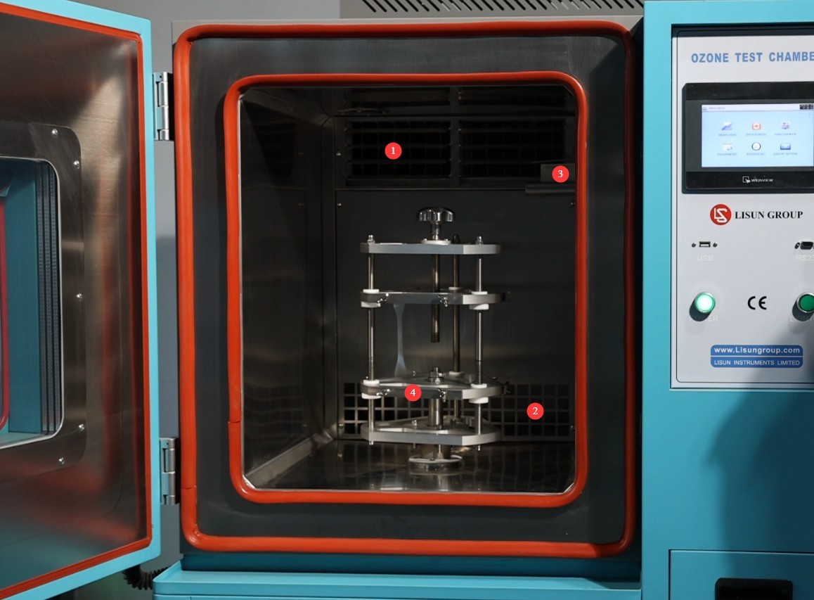
그림 5
2. 안전상의 주의
2.1 전기 안전
2.1.1 Power Connection Safety
The OTC-150A power cord is a single-phase, three-wire system, while the OTC-500A power cord is a three-phase, five-wire system. They must be connected to a dedicated power circuit; under no circumstances should multiple devices share the same circuit to prevent voltage fluctuations from affecting operation.
2.1.2 접지 요구 사항
The equipment must be reliably grounded, with a grounding resistance of ≤50 Ω. Do not use gas pipes, non-metallic water pipes, or the neutral wire as a substitute for the grounding wire. After grounding is complete, use a Grounding Resistance Tester to measure the grounding resistance. Power may only be applied after confirming that the resistance meets the requirements, to prevent electric shock, equipment malfunctions, or measurement errors caused by poor grounding.
2.1.3 Contraindications for the Procedure
Before connecting wires, performing maintenance, or replacing parts, you must turn off the main circuit breaker on the back of the equipment and disconnect the external power supply. Verify that there is no residual voltage before proceeding.
Do not touch the power switch, touch screen, or terminal blocks with wet hands to avoid electric shock; do not place cups or damp items near the equipment to prevent liquids from seeping into the electrical control cabinet.
Do not place any foreign objects (such as tools or paper) inside the electrical control cabinet to prevent dust or foreign objects from causing short circuits or damaging components.
장비가 작동 중일 때는 전원 코드나 신호 케이블을 연결하거나 분리하지 마십시오. 단락으로 인해 컨트롤러 또는 전기 부품이 손상될 수 있습니다.
2.2 작동 안전
2.2.1 Test Specimen Requirements
Only non-flammable, non-explosive, non-corrosive, and non-radioactive materials that meet the requirements may be tested; the improper placement of hazardous test specimens is strictly prohibited.
2.2.2 오존 보호
After the test is complete, you may activate the ozone chamber’s automatic exhaust function, or let it sit for a while (about half an hour) before opening the chamber door, to allow the ozone to fully dissolve in the water and avoid direct inhalation of ozone (ozone concentrations above 0.1 ppm can irritate the respiratory tract).
2.2.3 Operational Taboos
Do not open the chamber door while the equipment is running to prevent ozone leakage and sudden temperature changes that could affect the test.
Do not disassemble core components such as the ozone generator or sensors without authorization; modifying the equipment will void the warranty.
2.3 환경 안전
2.3.1 설치 요구 사항
The equipment must be placed in an air-conditioned room, with the ambient temperature maintained between 5 and 25°C (do not exceed 30°C to prevent overloading the refrigeration system), relative humidity below 85%, and no direct sunlight (to prevent aging of the enclosure and internal temperature fluctuations).
The installation environment must be well-ventilated and low in dust, and must be kept away from flammable or explosive gases (such as natural gas and liquefied petroleum gas) and corrosive gases (such as laboratory exhaust gases) to prevent component corrosion or the risk of fire.
The installation site must be free of strong air currents (such as direct airflow from an air conditioning vent) and strong electromagnetic fields (such as those from a Voltage Transformer).
Do not pile up clutter (such as cardboard boxes or reagent bottles) around the equipment; ensure proper air circulation to facilitate heat dissipation (especially for the condenser in the refrigeration system).
2.3.2 공간 요구 사항
A clearance of at least 1500 mm must be maintained between the equipment enclosure and the wall, as well as surrounding equipment (such as other test chambers or cabinets), to ensure that the side and rear panels can be opened for maintenance without impeding heat dissipation.
Allow at least 2000 mm of space in the direction the equipment door opens to prevent it from colliding with other objects when opened and to ensure easy access for loading and unloading test specimens.
Ozone may leak during operation of the test chamber; therefore, place the test chamber in a relatively open, well-ventilated area whenever possible.
2.3.3 Horizontal Placement
The equipment must be placed on a level surface and calibrated using a level: Place the level on a flat surface on top of the equipment and ensure the bubble is centered; if it is tilted, adjust the swivel casters at the bottom (or use shims) until it is level.
If the equipment is tilted, this may result in: ① Water leakage from the tank; ② Uneven hot air circulation, leading to deviations in test data; ③ Stress on the refrigeration system piping, increasing the risk of leaks.
2.4 기타
본 설명서에 나와 있지 않은 사항에 대해서는 주의를 기울여 진행하시거나 당사에 문의해 주십시오.
3. 시험 전 준비 사항
3.1 Filling the Water Tank
Open the machine’s water-filling drawer and check the drawer and the water tank (to check the water tank, you’ll need to open the panel on the right side of the machine) for any debris or standing water (clean the inside of the water tank before first use); if the automatic water refill port is connected to a water source, the tank will be refilled automatically;
The water tank and its drain valve are located as shown in the figure below. Note: After cleaning, the drain valve must remain closed during normal use.
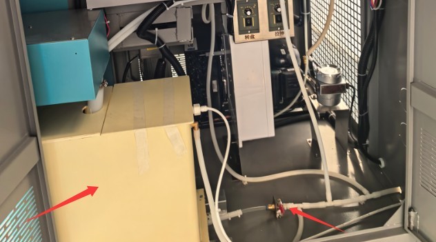
그림 6
The water tank must be filled with purified water (do not use tap water or bottled water). The water must be neutral (pH 6.5–7.5) to prevent limescale buildup from clogging the humidification system and corroding the water lines. When adding water, monitor the water level and fill the tank to 2/3 of its capacity (do not exceed this level to prevent overflow). Close the water tank drawer after refilling.
3.2 Starting Up The Ozone Test Chamber
Verify that the external power supply and ground connection are secure, close the equipment door, and turn on the circuit breaker on the back of the equipment (flip it upward to “ON”).
Press the “Power” button on the control panel and wait 5 seconds; the meter will automatically return to the main screen.
After powering on, check the instrument for any alarm indications. If an alarm is present, refer to Chapter 7 for troubleshooting; if no alarm is present, the instrument will enter standby mode, and you may proceed with parameter configuration.
Once powered on, the unit will automatically supply water to the humidification system. After 5–10 minutes, check the water level in the humidification probe’s reservoir (the gauze wrapped around the humidification probe must be completely saturated) and check the water level in the humidification boiler (open the right-side panel of the unit to verify), ensuring that the heating element inside the boiler is completely submerged in water(to prevent dry heating).
The locations of the humidifying boiler and the boiler water level sight glass are shown in the figure below:
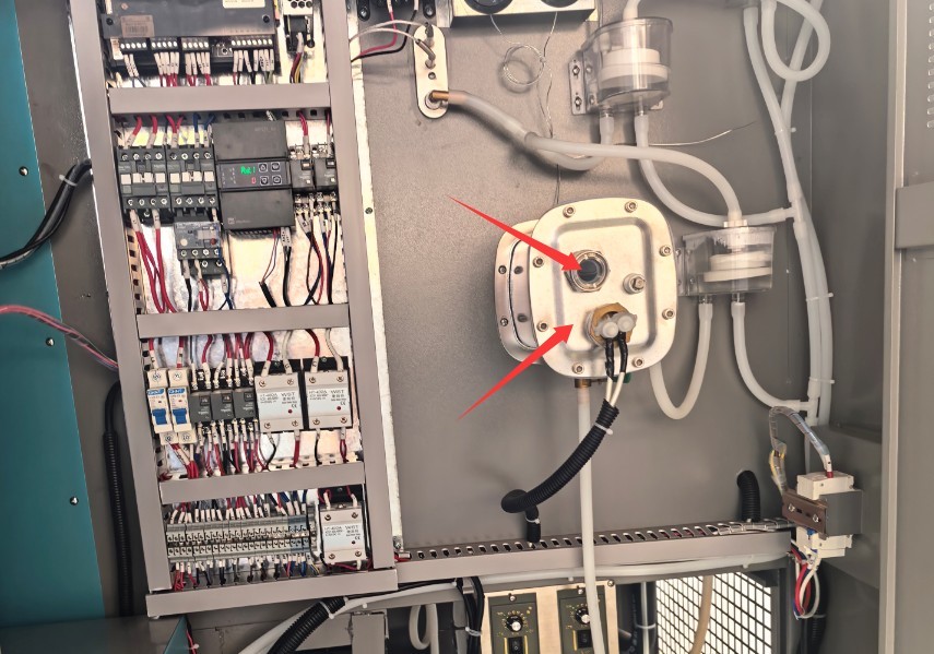
그림 7
3.3 샘플 설치
3.3.1 샘플 전처리
When selecting samples, prioritize common rubber products and ensure that the sample surfaces are free of oil and impurities.
For specimens requiring tensile testing, confirm the specimen length in advance to ensure it matches the height of the turntable tensile testing frame. See Section 3.3.2.2.
3.3.2 샘플 설치
3.3.2.1 Mounting of Non-Tensile Specimens
If tensile testing is not required during the test, the specimen may be placed on the turntable as desired.
3.3.2.2 Mounting Tensile Specimens
If stretching is required during the test, simply select “Stretch” on the touchscreen interface and then click “Run.” For instructions on using the touchscreen, refer to Chapter 4.
See the figure below. Platform No. ① moves up and down; when it reaches its highest point, click to stop it—at this point, it is closest to Platform No. ②. Then, use the knob indicated by the arrow to adjust the height of Platform No. ② according to the length of the sample. Finally, secure the sample between the two platforms as shown in the figure.
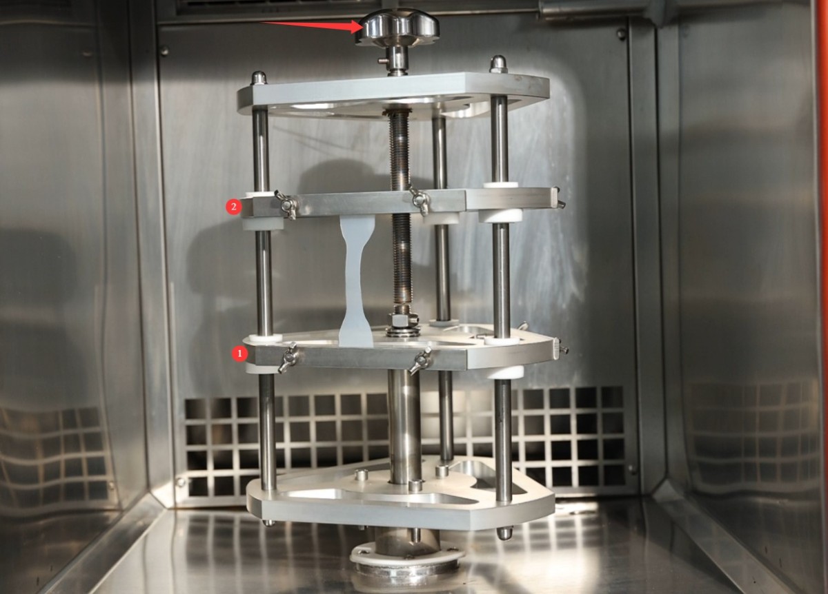
그림 8
To rotate the turret to accommodate more samples, simply select “Turret” on the touchscreen interface and tap “Run.” The turret will rotate; when it reaches the desired angle, tap “Stop” to load additional samples.
3.3.3 Closing the Cabinet Door
Gently push the cabinet door to ensure it fits snugly against the weatherstrip, with no gaps (if there are any gaps, check whether the door has sagged or the weatherstrip has deteriorated; make minor adjustments to the door hinges or clean the weatherstrip).
After closing the door, make sure the latch is securely engaged to prevent the door from opening accidentally during operation.
4. Program Operation via the Touchscreen on The Ozone Test Chamber
터치스크린 메인 메뉴 화면:
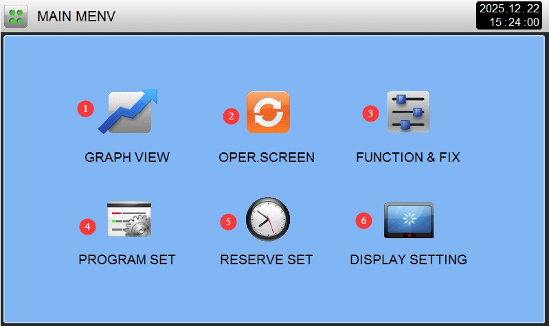
그림 9
① Curve Display: View historical temperature, humidity, and ozone concentration curves; supports data backup.
② Monitoring Screen: Displays real-time operating data and fault information.
③ Operation Settings: Select test modes (fixed values/programmed) and auxiliary parameters such as turntable and stretching.
④ Program Group Settings: Edit multi-segment test programs; up to 100 program groups can be configured;
⑤ Scheduled Settings: Set the scheduled start time and current time;
⑥ Display Settings: Switch languages (Chinese/English), configure power-off restart mode, and adjust screen brightness and screen saver duration.
4.1 작동 설정 화면 소개
"작동 설정" 화면으로 이동하세요.
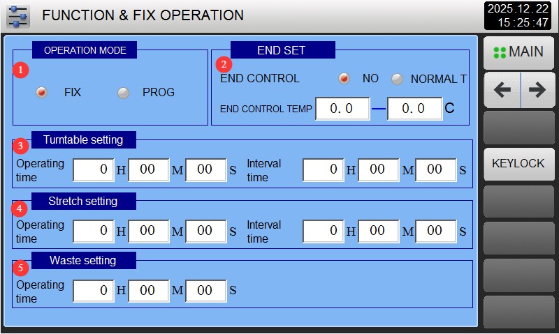
그림 10
① Select either the FIX test (fixed values) or the PROG test (program);
② To complete the setup, select either “No Action” or “Return to Ambient Temperature.” If you select “Return to Ambient Temperature,” you must set the ambient temperature range;
③ Set the turntable rotation time and interval; if continuous rotation is required, set the interval to 0;
④ Set the tensile test duration and interval; if continuous tensile testing is required, set the interval to 0;
⑤ Set the active exhaust time: If an air compressor is connected, you can set the active exhaust time here; generally, set it to 5 minutes. That is, after the test ends, the ozone chamber will use compressed air to actively exhaust any residual ozone from the test chamber and dissolve it into the water tank.
4.2 예약 설정 화면 소개
"일정 설정" 화면으로 이동하세요.
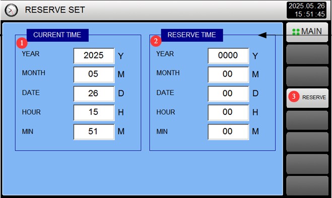
그림 12
① Current time;
② Set the scheduled time;
③ Click the “Schedule” button on the right, and the device will automatically run the selected test at the scheduled time.
4.3 Introduction to the Display Settings Screen
Go to the “Display Settings” screen:
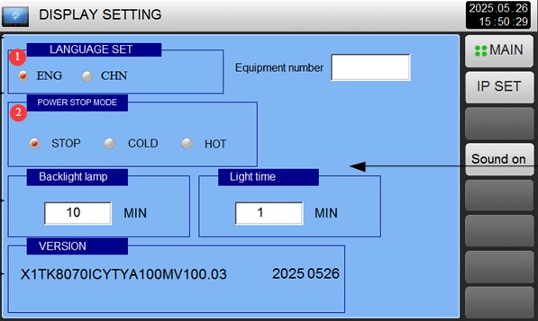
그림 13
① Select display language;
② Restart mode after an unexpected power outage. Stop: An operation that returns the system to a stopped state when power is restored after a power outage during operation; Cold Start: An operation that restarts the system from the first segment when power is restored after a power outage during operation; Hot Start: An operation that resumes operation from the segment where it left off before the power outage and restores the system to its pre-outage state when power is restored.
4.4 Fixed-Value Test Procedure (Continuous Operation with a Single Parameter)
4.4.1 Selection of Fixed-Value Tests
Go to the “Operation Settings” screen and select “FIX.”
4.4.2 Introduction to the Calibration Test Monitoring Screen
Go to the “Monitoring Screen”:
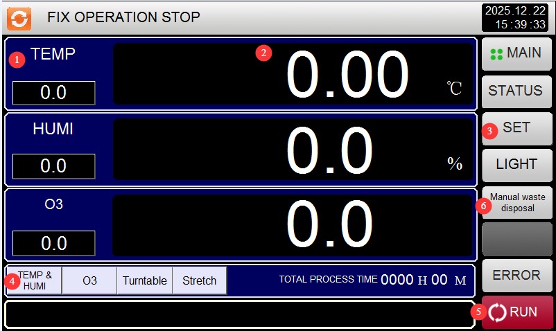
그림 14
① The left column displays the set values for temperature, humidity, and ozone concentration;
② The center of the screen shows the current values in the test chamber;
③ Set: Tap to enter the parameter settings screen;
④ Current control type. From left to right, these are: Temperature and Humidity, Ozone, Rotating Table, and Tensile Test. Please tap the desired function to highlight it in red;
⑤ Run: Tap to start or stop the test;
⑥ If the active exhaust time was not set in Section 4.1, you can tap this button after the test ends to manually activate the active exhaust function.
Note: Please do not enable the active exhaust system during testing.
4.4.3 Setting Fixed-Value Test Parameters
Click “Settings” to open the settings screen:
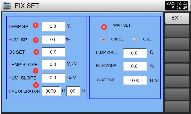
그림 15
① Temperature setting;
② Humidity setting;
③ Ozone concentration setting;
④ Temperature and humidity ramp rates: Unless otherwise specified, set all values to 0; the unit will operate with automatic ramp rates. Setting other values may cause the unit to malfunction;
⑤ Wait Setting: If the wait function is selected, the test chamber will not begin calculating the test time until the set temperature and humidity are reached. To use the wait function, you must simultaneously set the wait tolerance (the test is considered complete if the values fall within this tolerance range) and the wait time (if the test chamber has not reached the target temperature and humidity by the end of the wait time, it will automatically begin calculating the test time).
4.5 Program Testing Procedures (Automatic Switching Between Multiple Parameter Sets)
4.5.1 Selective Testing
Go to the “Operation Settings” screen and select “Program (PROG).”
4.5.2 Introduction to the Program Group Settings Screen
Go to the “Program Group Settings” screen:
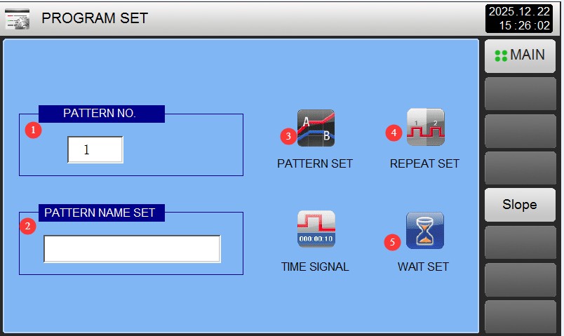
그림 16
① Program Group: Can be set to 1–100;
be sure not to use a number that conflicts with existing program group numbers. ② Test Name: You can customize the test name for this program.
③ Program Group Edit: Click to edit program group parameters.
④ Cycle Settings: Click to edit the program group’s cycle mode.
⑤ Wait Settings: Click to configure the wait function and parameters.
4.5.3 Introduction to the Program Group Edit Screen
Go to the “Program Group Editor” screen:
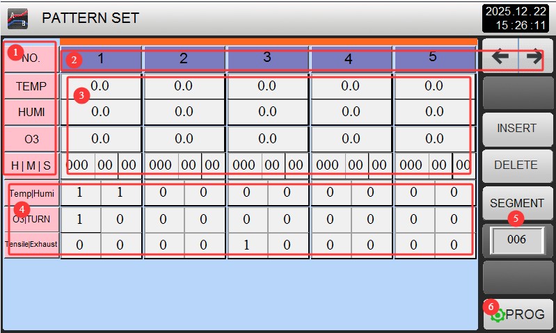
그림 17
① Control Type: From top to bottom: temperature, humidity, ozone concentration, and test duration;
② Test Segment Number: Click the left or right arrow keys to switch to other test segments;
③ Parameter Settings: Set the required temperature, humidity, ozone concentration, and test duration for the corresponding test segment;
④ Use the default values for all parameters here; no adjustments are necessary;
⑤ Number of Segments: Enter the number of test segments to run in this program group. For example, if you only want to run the first 4 segments, enter 4;
⑥ Return to the program group settings screen.
Note: Each set of temperature and humidity parameters must be configured with the same two segments. The first segment is the transition period—the time it takes for the equipment to reach the set parameters—which should be set to 1 minute (since the program includes a wait function, this will actually take longer than 1 minute; the equipment will reach the set parameters as quickly as possible and then automatically proceed to the next segment). The second segment is the actual test duration.
4.5.4 Introduction to the Cycle Settings Screen
"사이클 설정" 화면으로 이동하세요.
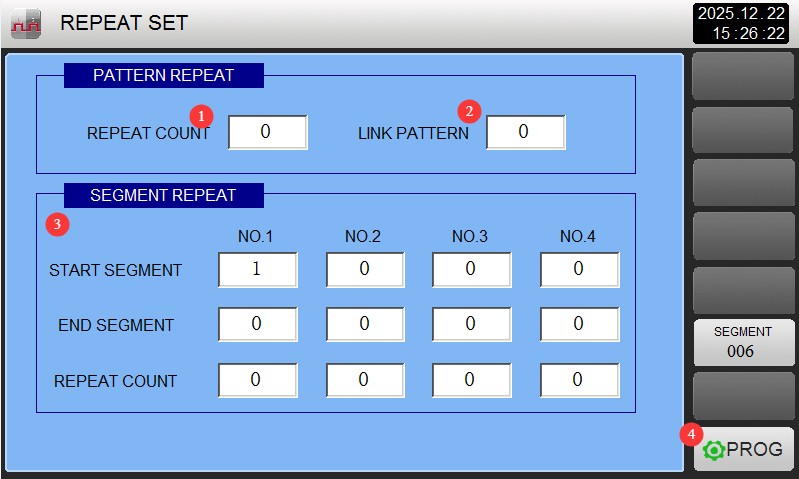
그림 18
① Loop Count: Indicates whether the current program should run in a loop. If no loop is needed, enter 1; the program will then run once and terminate.
② Program Link Settings: If you want this program to automatically link to another program for testing after it finishes running, enter the corresponding program number. If not, enter 0.
③ Segment loop settings: If you want to loop through segments 1 through 2 of this program twice and segments 3 through 4 three times, set the three fields in the first column to 1, 2, and 2, respectively; and set the three windows in the second column to 3, 4, and 3, respectively. This means the sequence of segments during the entire program test will be 1, 2, 1, 2, 3, 4, 3, 4, 3, 4, 5…, etc. If this function is not needed, set all windows to 0.
④ Return to the program group settings screen.
4.5.5 Introduction to the Wait Settings Screen
Go to the “Waiting Settings” screen:
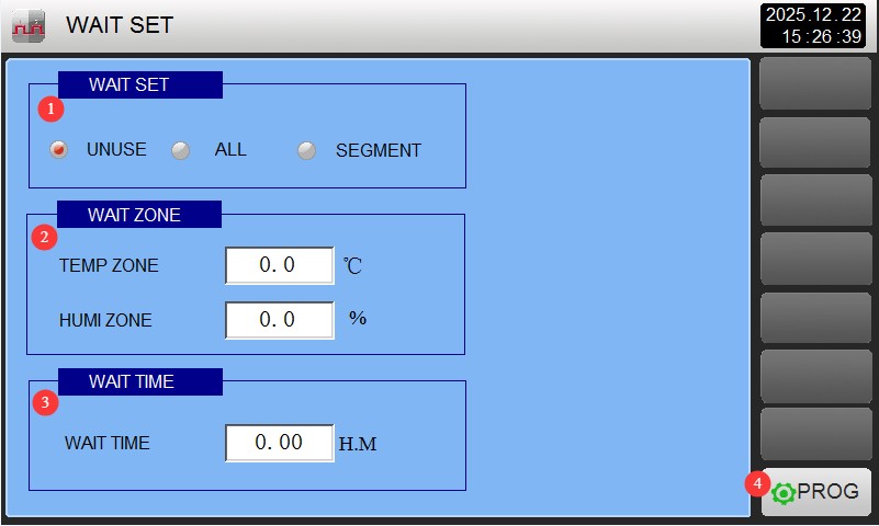
그림 19
① Under normal circumstances, select “All,” which enables the wait function for all segments;
② Wait Range: For example, if the wait range temperature is set to 0.5 and the target temperature for the transition stage is set to 50 degrees Celsius, when the test chamber temperature reaches within the range of 49.5 to 50.5 degrees Celsius, it is deemed to have reached the target temperature, and the system will proceed to the next stage;
③ Wait time: You can set the maximum wait time as needed. For example, if the wait time is set to 2 hours, and the parameters still do not reach the target value after the unit has waited for 2 hours, it will automatically proceed to the next stage.
4.6 Operational Testing and Monitoring
4.6.1 운영 테스트
Go to the “Monitoring Screen,” click the “Run” button in the lower-right corner, and you can run the currently selected fixed-value or program test.
4.6.2 실시간 데이터 모니터링
Use the “Monitoring Screen” to view the setpoints and actual values for temperature, humidity, and ozone concentration.
Check the operating status of functions such as the turntable and stretching (ON is red; OFF is dark gray).
4.6.3 문제 해결
If the test chamber malfunctions and an alarm message appears on the touchscreen, the system will automatically switch to the alarm screen. Please refer to Section 7 and use the alarm code to troubleshoot the issue.
5. 테스트 후 절차
5.1 Stop Testing
After the test is complete, or after manually stopping the test, you must actively vent the waste for at least 5 minutes or let it stand for at least 30 minutes to allow any residual ozone inside to fully dissolve in the water.
5.2 Shutting Down the Equipment
Press the green button below the touchscreen to turn off the device. Once the screen goes dark, turn off the circuit breaker on the back. Do not leave the operating area until you have confirmed that the device is completely de-energized.
5.3 Sample Preparation and Equipment Cleaning
5.3.1 샘플 준비
Wear a medical mask and gloves when opening the chamber door (to avoid irritation from residual ozone), and remove the sample. Record any changes in the sample’s appearance, hardness, and other characteristics; it is recommended to take photos for archiving purposes to facilitate subsequent analysis.
5.3.2 Equipment Cleanup
Wipe down the interior of the chamber with a dry cloth to remove any residual impurities from the samples. Close the chamber door to keep the interior dry.
6. 장비의 일상 유지보수 및 관리
6.1 정기 점검
6.1.1 주간 유지보수
Wipe the device’s exterior with a soft cloth dampened with a neutral detergent; avoid using corrosive liquids such as alcohol.
Check whether the turntable rotates smoothly and whether there is any sticking.
6.1.2 월별 유지보수
Completely drain and replace the water in the tank to prevent scale buildup; inspect the turntable bearings and apply grease to ensure smooth operation.
Check the gauze on the humidity probe; if its absorbency has decreased, replace it promptly.
6.1.3 Maintenance Every 6 Months
After turning off the power, open the electrical control cabinet and use a brush to remove dust to prevent short circuits.
Check the terminal blocks for looseness and retighten them; calibrate the temperature/humidity sensors; if the deviation exceeds ±1°C, professional calibration is required.
To remove dust from the condenser fins, use an air gun to blow it off.
6.2 장기 보관 및 유지 관리
6.2.1 Pre-treatment Storage
Run the “Dry” program (temperature 60°C, humidity 0%, 2 hours), drain and clean the water tank, and unplug the power cord.
Thoroughly wipe down the inside and outside of the equipment with a dry cloth to ensure there is no moisture or residue left behind.
6.2.2 보관 중 유지 관리
Power it on once a month (for 30 minutes) to prevent the capacitors from deteriorating.
Place a desiccant inside the box to prevent moisture; check the desiccant regularly and replace it promptly.
The storage environment must meet the installation requirements; avoid direct sunlight, humidity, and severe vibrations.
7. 문제 해결 및 일반적인 문제 해결 방법
7.1 Touchscreen Error Messages
If a fault occurs while the equipment is running, a fault alert will appear on the screen. You can click the “Fault” button to access the “Real-Time Fault Display Screen” and view the specific fault type.
7.2 일반적인 문제 및 해결 방법
7.2.1 Electrical Faults
No display on the touchscreen: Check whether the power is on and whether the circuit breaker has tripped. If the fuse has blown, replace it with a fuse of the same specification.
Communication Failure (Displays “PLC no response”): Check that the communication cables are intact and securely connected, then try unplugging and replugging the cables.
7.2.2 Test Parameter-Related Faults
Temperature not within specifications: This may be due to a damaged heating element or a faulty sensor. First, clean the sensor to troubleshoot the issue; if that does not resolve the problem, contact LISUN Customer Service to have the heating element inspected.
Significant fluctuations in humidity: Replace the gauze in the humidity sensor if it has failed, refill the water tank to the specified level, and ensure the water quality meets the requirements.
Ozone concentration is 0: Check whether “Ozone” is set to red (enabled) in the control settings. If the ozone generator is not running, contact LISUN customer service for repair.
7.2.3 Mechanical Failures
Turntable/Stretching Function Not Working: This may be caused by a motor overload or a jammed transmission component. Disconnect the power for 30 minutes, then restart the machine; remove any foreign objects and apply lubricant. If the problem persists, contact customer service.
Poor drainage: Check the drain hose for clogs or kinks, make sure the hose is positioned below the drain outlet, and clear any debris from the drain outlet.