
 영어
영어 中文简体
中文简体 Русский
 Español
 Português
 Türkçe
 العربية
 Deutsch
 Polski
 Italiano
 Français
 한국어
한국어 ไทย
ไทย Tiếng Việt
 日本語
日本語





























전자파 차폐 캐비닛
사용자 설명서
적용 할 수있는 LISUN 모델: SDR-2000B、SDR-2000L、SDR-4000B、SDR-5000B,SDR-800S
1. Sector Classification and Positioning
Using the layout diagram, identify all the panels. The G series consists of floor panels, the W series consists of wall panels, and the F series consists of ceiling panels. Some panels on the layout diagram are labeled identically; these panels have the same physical structure and dimensions and can be swapped in any order. Panels with unique numbers have fixed positions and must be placed exactly as shown on the layout diagram.
2. Cleaning and 치료
Clean the side of the panel with the screw holes using alcohol to remove all dust and oxidation. If necessary, gently sand the surface with sandpaper to ensure good electrical conductivity at the contact points.
3. 준비 the Materials
Find the conductive lining and screws and nuts in Box No. 4.
4. Installation Steps for the Conductive Liner (Do Not Tighten Yet)
Refer to the attached video for instructions on installing the conductive liner and screws and nuts. The width of the panel’s surface where the screw holes are located is 50 mm, and the width of the conductive liner is 25 mm. Place the conductive liner in the center of the screw hole, pierce the liner with a sharp object, then thread the screw through the panel first, through the conductive liner, and finally through the panel on the other side, then secure it with a nut. Note: Do not fully tighten the screws and nuts; simply turn the nut 2–3 turns to ensure it does not come loose. Once all panels and the shielding door have been fully assembled and the shielded room enclosure is fully formed, tighten all screws completely at that time.
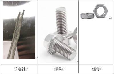
그림 1
5. 최적의 Locking Timing
There are a total of four waveguide windows in Box No. 4.
The waveguide windows are located on panels F1 and F6. Each panel has two square holes; align the waveguide windows with the square holes and position them so that they protrude from the exterior of the equipment room in the direction of their thickness. Next, use an electric drill with a 10mm drill bit to drill through both the waveguide window frame and the F1/F6 panels simultaneously. We typically drill a hole every 10 cm, but it’s fine to drill more if needed. After drilling the holes, clean the contact surfaces of the frame and the F1/F6 panels with alcohol to ensure electrical conductivity. Then secure the waveguide windows with conductive pads and screws and nuts, using a method similar to that used for assembling the panels.
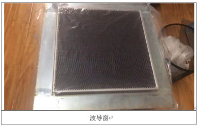
그림 2
6. 필터 설치
Determine the filter installation location. Typically, we install the filter on the ceiling of the equipment room; the specific location should prioritize ease of wiring—taking into account both the entry point of the external power cable and the placement of the internal distribution panel. Use a hole saw to cut a hole in the server room ceiling (or another location); the hole should be the same size as the filter’s waveguide. Clean the cutout area to ensure electrical contact between the filter and the panel. Feed the waveguide through the panel, then tighten the washer nut on the inside of the panel.
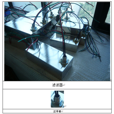
그림 3
7. 바닥 설치
Floor Installation: Floor accessories are in Box 3
First, place the floor bases on the floor inside the shielded room, spacing them approximately 60 cm apart. Then, use screws and crossbeams to connect the bases to each other. Next, place the anti-static flooring into the frame formed by the crossbeams. When you reach the wall, the entire floor panel may not fit, so you will need to cut it to size based on on-site measurements.
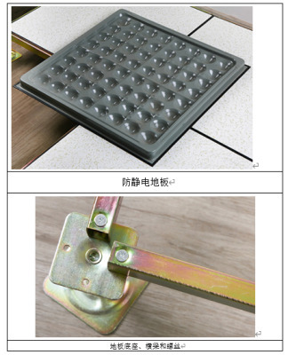
그림 4
8. 전기 설치
Install electrical switches, outlets, and lighting according to your daily habits. Typically, we run the filter wiring into the indoor distribution panel, and then run wires from the distribution panel out to the switches, outlets, and lighting fixtures. During construction, be sure not to drill holes in the surface of the equipment room enclosure; if screws are needed, they must be driven only into the L-shaped flange on the inner side of the panels. The filter contains a high-capacity capacitor; please note the following two precautions: A. Before powering on the equipment room, ensure it is reliably grounded with a grounding resistance of ≤2Ω; the grounding wire can be soldered to the top of the equipment room. B. Do not install a residual current device (RCD) upstream of the filter (a circuit breaker is acceptable); otherwise, the RCD may trip.
9. 중요 사항
Note: Any other materials included in the shipping box are decorative finishing materials and are optional. Users may customize the interior according to their own needs; the only thing to keep in mind is not to drill holes in the shielded room. If you need to drill holes, please contact us.