
 영어
영어 中文简体
中文简体 Русский
 Español
 Português
 Türkçe
 العربية
 Deutsch
 Polski
 Italiano
 Français
 한국어
한국어 ไทย
ไทย Tiếng Việt
 日本語
日本語





























서지 발생기
사용자 설명서
적용 할 수있는 LISUN 모델: SG61000-5,SG61000-5SB
1. 제품 개봉 및 기본 사용법 익히기
1.1 주요 기술 사양
| LISUN 모델 | SG61000-5SB | SG61000-5 |
| Turn-On Voltage Waveform | 1.2/50 μs ± 20% | |
| 단락 전류 파형 | 8/20 μs ± 20% | |
| 출력 임피던스 | 2Ω 및 12Ω | |
| 출력 전압 범위 | 0~4.8kV ±5% | 0~6kV ±5% |
| 출력 전류 범위 | 0–2.4 kA ±5% | 0–3 kA ±5% |
| Number of surges | 1-9999 번 | |
| 극성 | Positive Terminal, Negative Terminal, and Fully Automatic | |
| 상 | Asynchronous, Synchronous: 0°–360° or specified angle testing | |
| 특별기능 | N/A | Brand-new free upgrade: Includes built-in Voltage Probe and current attenuator probes, as well as an electronic oscilloscope, allowing you to view output waveforms directly on the touchscreen! |
| 운영 절차 | LCD touchscreen input, built-in Android operating system | |
| 크기 (폭 x D x 높이) | 44 × 45 × 35 cm | |
| 총 중량 | 약 30 kg | |
| Coupling Decoupling Network (Built-in CDN) | AC 240 V/16 A Single-Phase CDN | |
| EUT Isolation Transformer (External, Optional) | LISUN ITEU-SP4K (220V single-phase) or ITUS-SP2K (110V) | |
1.2 개봉 및 내용물 확인
1.2.1 포장 해제 및 육안 검사
기기를 개봉할 때는 날카로운 도구로 케이스에 흠집이 나지 않도록 조심스럽게 다루십시오. 개봉 후에는 먼저 기기 외관을 검사하여 눈에 띄는 변형이나 찌그러짐이 없는지, 버튼이 손상되었거나 헐거워지지 않았는지 확인하십시오.
If you notice any damage or deformation to the equipment or accessories, do not turn on the power. Please contact us immediately.
1.2.2 호스트 및 액세서리
Host-type, see Figure 1-1.
| 번호 | 주의 사항 |
| ① | SG61000-5 서지 발생기 |
| ② | ITEU Series Isolation Transformers, used to power samples via lightning surges |
| ③ | PD-E01, EUT sample box, designed to prevent splashes from the EUT during testing; when opened, the PD-E01 sample box automatically disconnects the EUT cables to prevent accidental electric shock |
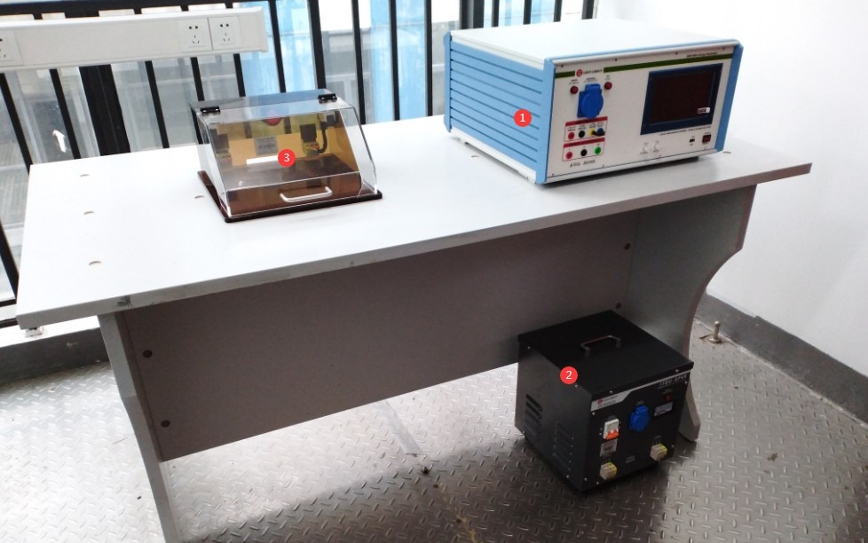
그림 1-1
Note 1: Surge Generators must be used in conjunction with Isolation Transformers to protect the power grid; this manual uses the ITEU series of Isolation Transformers as an example.
Note 2: The PD-E01 sample box is optional. During testing, samples may be severely damaged by surges or even cause parts to fly off; place the sample in the sample box to ensure a safe testing environment. The dimensions of the sample box can be customized to fit the size of the EUT sample.
Standard accessories, as shown in Figures 1–2: ① Isolation Transformer output cable, connecting the Isolation Transformer’s output terminal to the CDN input terminal of the Surge Generator; ② Isolation Transformer power cord; ③ Surge Generator power cord; ④ EUT test lead, connecting the Surge Generator to the test specimen;⑤ Banana plug cable, for backup; ⑥ Ground wire, used to connect to the PGND protective ground terminal; ⑦ Coaxial cable, used to connect to an external oscilloscope for monitoring surge waveforms; ⑧ Discharge tube, used to check whether the equipment is outputting surges in the event of a malfunction.
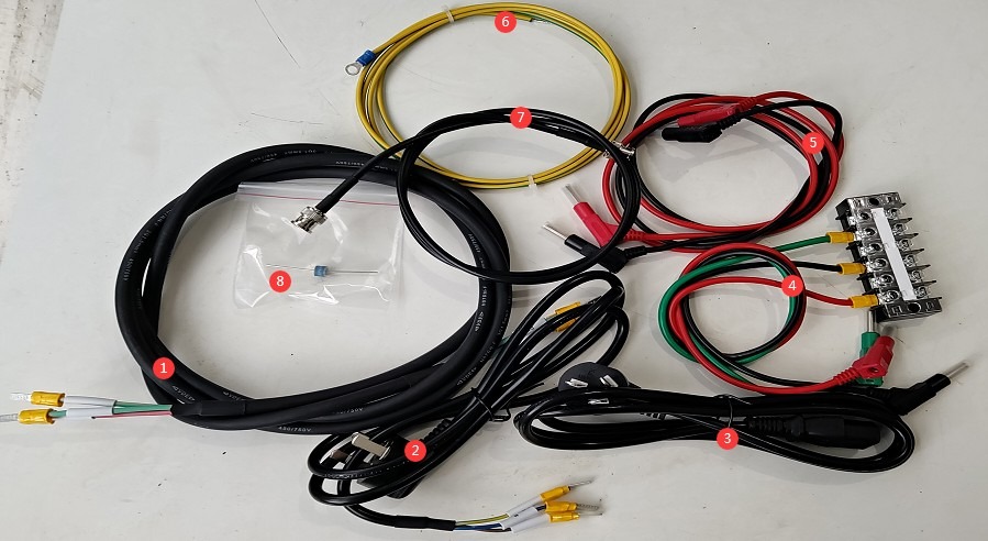
그림 1~2
1.3 전자 문서 다운로드
전자 사용자 설명서, 교정 인증서, 보증서 및 기타 문서의 다운로드 링크는 제품 발송 시 이메일로 이미 보내드렸습니다. 가능한 한 빨리 다운로드해 주시기 바랍니다. 만약 이메일을 받지 못하셨다면, 저희에게 연락하여 다운로드 링크를 다시 요청해 주십시오.
2. 안전상의 주의
2.1 Placement Guidelines
Ensure the ambient temperature is between 15°C and 35°C, relative humidity is between 10% and 60% (no condensation), and atmospheric pressure is between 86 kPa and 106 kPa to prevent damage caused by high-voltage short circuits or moisture ingress;
The premises must be free of strong electromagnetic interference, corrosive gases, flammable or explosive materials, and dust, and must be well-ventilated to prevent electrical sparks from causing hazards;
Place it on a stable workbench; avoid tilting or inverting it, and keep it away from sources of vibration;
Isolation Transformer: Keep it at least 0.5 meters away from the main unit to prevent electromagnetic coupling interference;
The equipment must be placed at least 1000 mm away from walls and surrounding structures (such as other testing equipment and shelving) to facilitate maintenance; at least 2000 mm of space must be left in front of the equipment to ensure smooth operation, and there must be no obstructions in the surrounding area.
2.2 High-Voltage Safety Standards
2.2.1 보안 검색
Verify that the equipment’s power supply voltage matches the mains voltage: AC 220 V ±10% (AC 110 V available upon request), 50/60 Hz. Ensure that the power supply is properly grounded and that the grounding wire is free of damage or looseness;
Grounding Requirements: The host unit’s protective grounding terminal (PGND) must be connected to ground, with a grounding resistance of ≤1 Ω, to ensure safe discharge of high voltage;
Operators must have dry hands and must not wear any metal jewelry.
2.2.2 운영 절차에 대한 안전 요구 사항
Operators must undergo professional training and be familiar with this manual and the relevant standards. Non-professionals are prohibited from operating or disassembling the equipment. The equipment contains high-voltage circuits; opening the cover may pose an electric shock hazard. Contact the manufacturer’s technical staff for repairs.
The equipment generates high voltages (up to 6 kV) and high-current surges during operation. Do not touch the pulse output connector, the EUT terminals, or the CDN port under any circumstances.
During testing, unauthorized personnel must not remain within 1 meter of the EUT to prevent accidental electric shock or interference from electrical discharges.
Before switching connections or replacing the EUT, you must first ensure that the high-voltage output is turned off (the HV indicator light is off) and wait at least 5 minutes to ensure that the internal high-voltage capacitors are completely discharged.
Do not eat or drink during the test to prevent accidents caused by electric shock.
여러 사람이 참여하는 경우, 역할과 책임을 명확하게 정의하고 오류를 방지하기 위해 테스트 시작 전에 서로 확인해야 합니다.
2.3 Emergency Response Measures
In the event of an electric shock: Immediately shut off the main power supply to the equipment, move the operator to a safe area, administer first aid if necessary, and contact medical personnel.
Equipment Malfunction (Smoke, Unusual Noises, Unusual Odors): Immediately shut down the equipment and disconnect the power supply; disconnect all wiring; do not turn the equipment back on; contact the manufacturer for repairs.
Abnormal surge output: Pause the test, contact the manufacturer for troubleshooting, and do not touch the test port directly with your hands.
2.4 기타
본 설명서에 나와 있지 않은 사항에 대해서는 주의를 기울여 진행하시거나 당사에 문의해 주십시오.
3. 시험 전 준비 사항
3.1 Hardware Wiring Sequence
Connect ground terminal ① on the back of the host to ground, as shown in Figure 3-1.
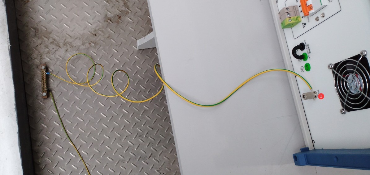
그림 3-1
The two ports labeled ① and ② on the front of the main unit are both built-in CDN output ports that can be connected to the EUT (Equipment Under Test). Select one based on the EUT’s current and wiring configuration; see Figure 3-2.
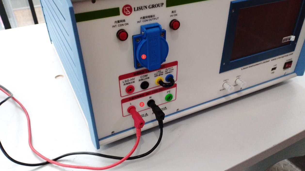
그림 3-2
For safety reasons, the EUT may be placed in the sample box, as shown in Figure 3-3.
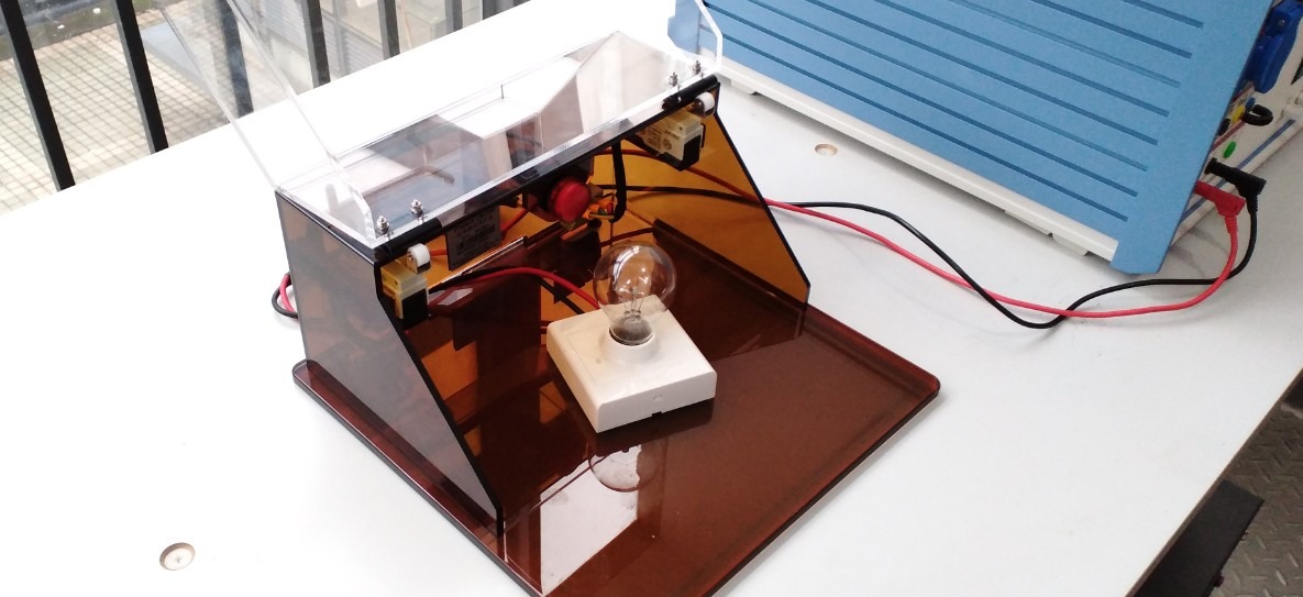
그림 3-3
Note 1: Before testing, verify that the EUT is in normal operating condition and meets the product’s rated operating conditions.
Note 2: The EUT should preferably be placed on the left side of the equipment so that the EUT connection cables do not need to pass in front of the surge generator’s touchscreen, thereby preventing interference with the touchscreen during the test.
For the Isolation Transformer wiring, see Figures 3-4 and 3-5. Depending on the EUT’s rated current and wiring configuration, connect one of the output ports (① or ②) to the built-in CDN input port (④) on the back of the host unit. Port ③ is the input port; connect the Isolation Transformer’s power cord to it.
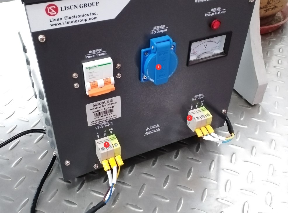
그림 3-4
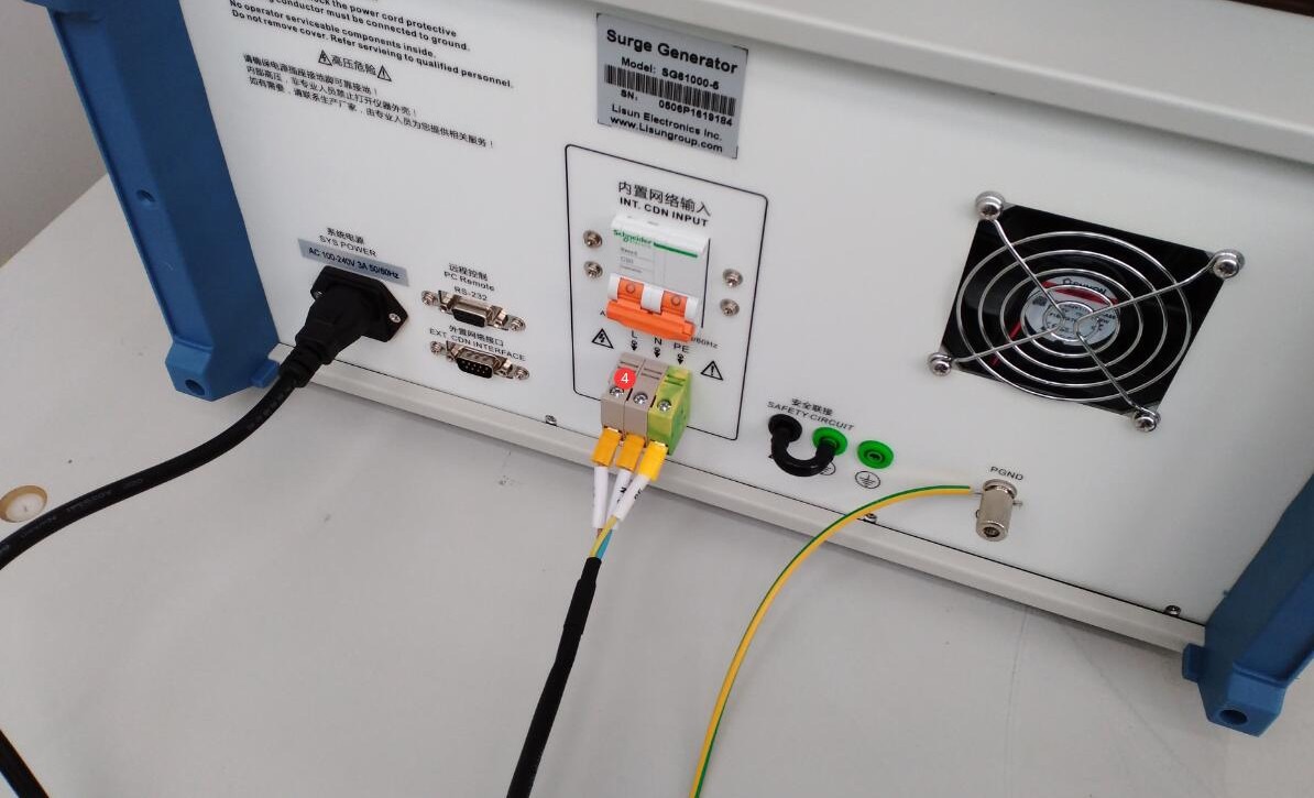
그림 3-5
Next, connect the power cords of the Surge Generator and the Isolation Transformer to an appropriate power source.
Note: The Isolation Transformer is used only to supply power to the EUT via the host’s built-in CDN; the Surge Generator’s own power supply does not need to be connected to the Isolation Transformer.
3.2 Confirmation of Test Parameters
3.2.1 Selection of Test Level
Based on the EUT installation environment and product standards, select the corresponding test level (priority levels are listed in the table below); lower levels must meet compatibility requirements:
| 테스트 레벨 | Breakdown Test Voltage (±10%) | 적용 가능한 시나리오 |
| 레벨 1 | 0.5 kV | A well-maintained indoor environment |
| 레벨 2 | 1.0 kV | Typical Indoor Environment |
| 레벨 3 | 2.0 kV | Outdoor or semi-outdoor environments |
| 레벨 4 | 4.0 kV | 혹독한 야외 환경 |
| X- 클래스 | Specific Voltage | Special scenarios specified in product standards |
3.3 Equipment Warm-up and Self-Test
Turn on the power switch on the front panel of the host; the device enters standby mode, the power indicator light turns on, and the cooling fan starts up.
Wait 5 minutes for the device to warm up, and check that the touchscreen is displaying normally and shows no error messages.
4. 터치스크린 프로그램 소개
The program’s initial screen, as shown in Figure 4-1.
| 번호 | 주의 사항 |
| ① | Settings Interface for the Built-in Digital Oscilloscope |
| ② | General Usage Guidelines (This feature is still under development; please do not access it or perform any actions at this time) |
| ③ | System Information Screen |
| ④ | 중국어와 영어 간 전환 |
| ⑤ | 프로그램 인터페이스 |
| ⑥ | Surge Test Interface |
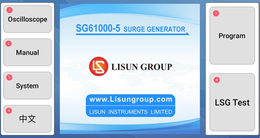
그림 4-1
참고 : SG61000-5SB does not have an oscilloscope function, while the SG61000-5 않습니다.
4.1 Oscilloscope Function Settings Interface
See Figure 4-2. Simply check all the boxes, and the current surge waveform will be displayed automatically after each surge test is completed.
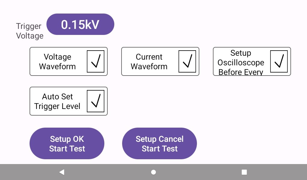
그림 4-2
4.2 Program Interface
Used to create new programs or manage existing ones; see Figure 4-3.
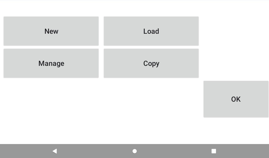
그림 4-3
If you need to test the program, simply enter all the parameters to be tested step by step as needed and then save them, as shown in Figure 4-4.
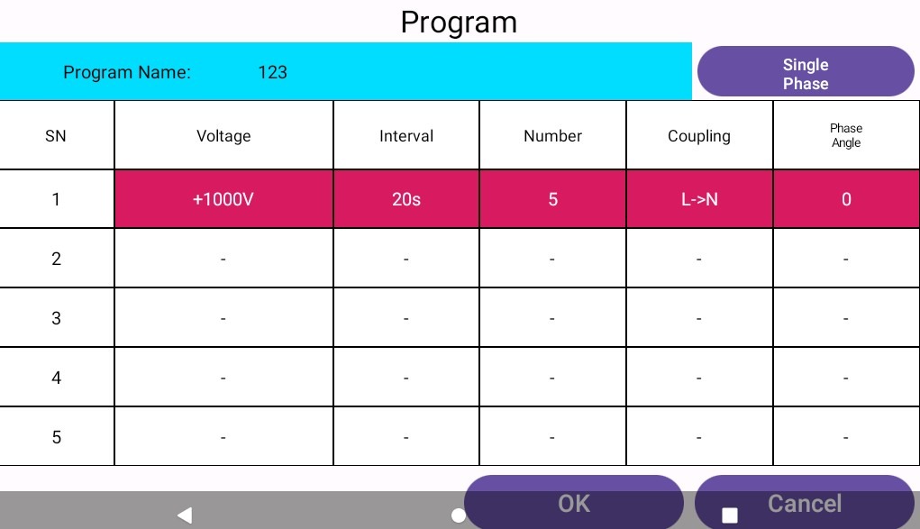
그림 4-4
4.3 Surge Test Interface
그림 4~5을 참조하십시오.
| 번호 | 주의 사항 |
| ① | Surge Voltage and Polarity Settings |
| ② | Surge Interval Setting |
| ③ | Surge Count Setting |
| ④ | Surge Coupling Direction Settings |
| ⑤ | Surge Phase Angle Setting |
| ⑥ | Common-Mode Impedance Selection (Default: 12 Ω; optional: 2 Ω; no setting required for differential mode—fixed at 2 Ω) |
| ⑦ | EUT Parameter Monitoring Settings |
| ⑧ | You can run the edited program directly to test it. |
| ⑨ | EUT Voltage and Current Display |
| ⑩ | Click to turn on (or off) the EUT’s power |
| ⑪ | Click to start or stop the surge test |
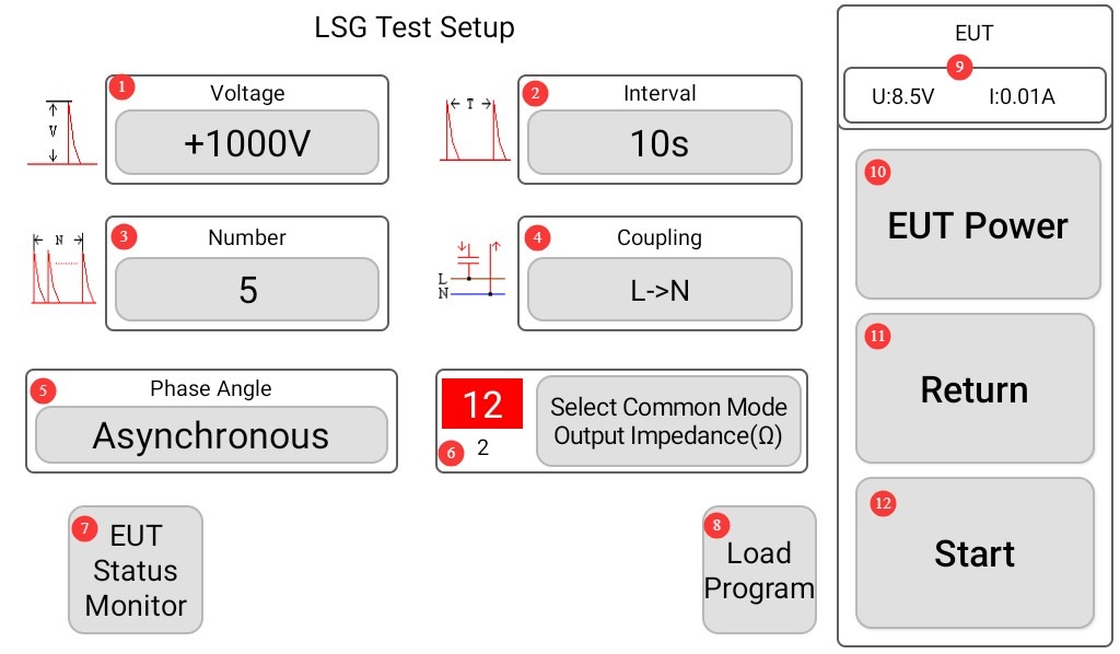
그림 4~5
Note: To automatically display the current surge waveform on the screen, set the surge interval to at least 10 seconds; otherwise, the program will not have enough time to display the surge waveform.
4.3.1 Surge Coupling Direction Settings Interface
You can select a single coupling direction, or click “Auto” to select multiple coupling directions simultaneously; see Figures 4–6.
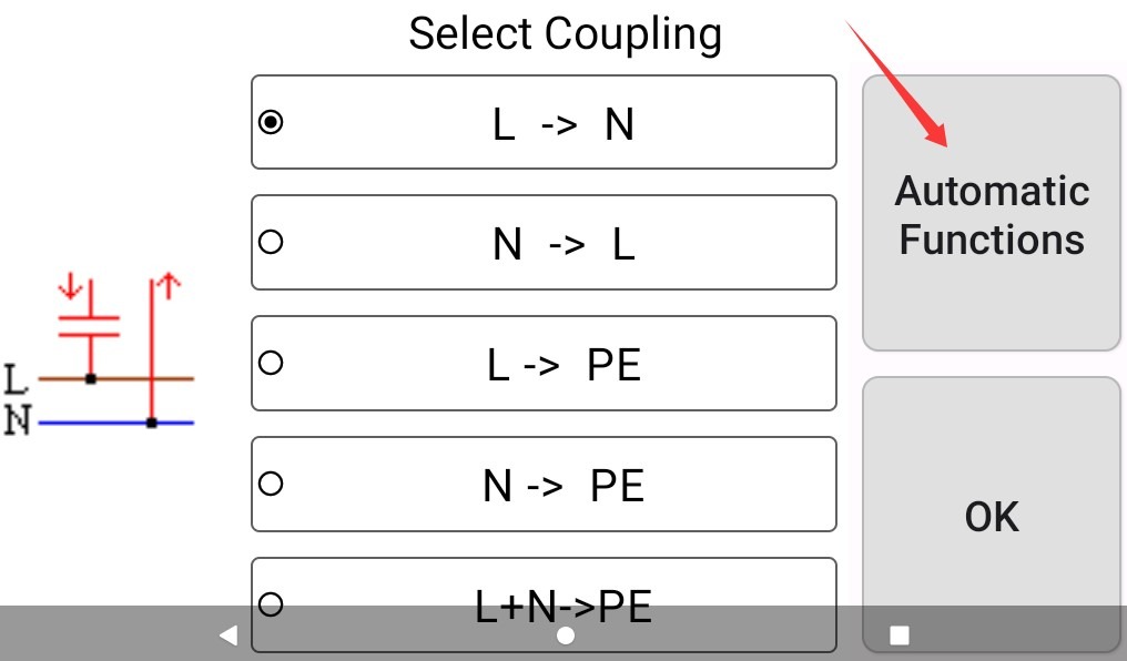
그림 4~6
On the “Automatic Functions” screen, you can select various combinations of coupling directions, or click “General” to return to selecting a single coupling direction, as shown in Figure 4-7.
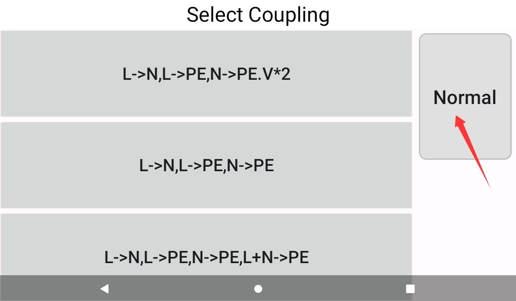
그림 4-7
4.3.2 Surge Angle Settings Interface
You can select asynchronous, a single surge angle, or click “Auto” to select multiple coupling angles simultaneously, as shown in Figure 4-8.
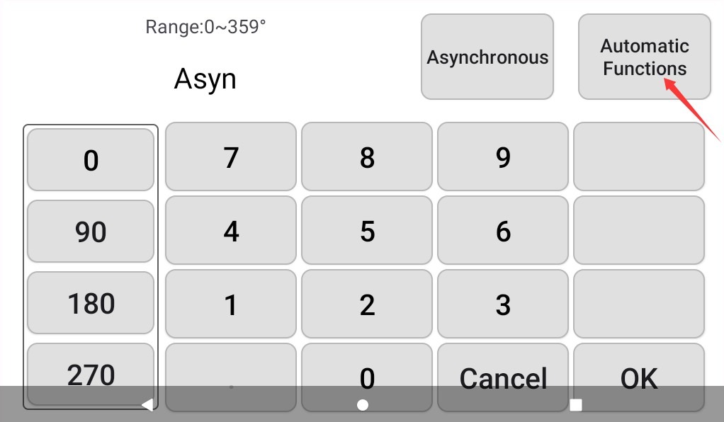
그림 4-8
In the “Auto Function” interface, you can select from a variety of angle combinations. Click the button marked in the image below to return; see Figure 4-9.
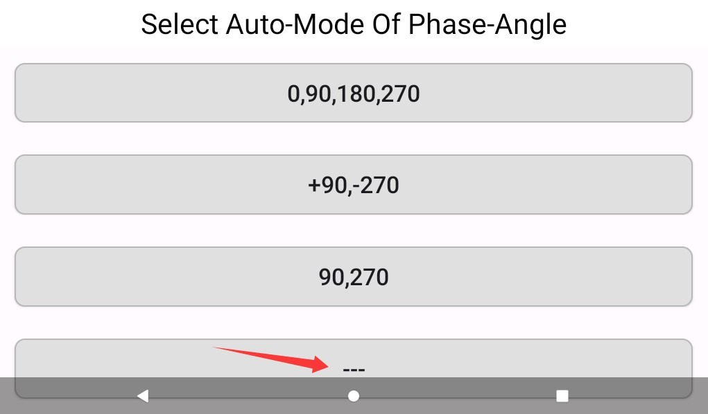
그림 4-9
4.3.3 EUT Parameter Monitoring Settings Interface
그림 4-10를 참조하세요.
| 번호 | 주의 사항 |
| ① | √ indicates that EUT parameters are monitored; × indicates that EUT parameters are not monitored |
| ② | √ Indicates that surge peak data is monitored; × indicates that surge peak data is not monitored. |
| ③ | √ The device automatically stops the surge test when the EUT’s voltage and current data exceed the set limits. |
| ④ | √ When the peak surge voltage or current exceeds the set limits, the device automatically stops the surge test. |
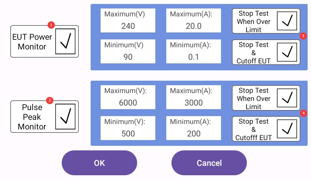
그림 4-10
Note 1: Users may choose whether or not to monitor EUT parameters and surge peak data during the test; this does not affect the surge test.
Note 2: If you select option ③ or ④, the surge test may be unexpectedly interrupted due to the triggering of a protection mechanism. Please choose carefully and set appropriate limits.
5. Surge Testing
5.1 운영 절차
After all the parameters in the touchscreen program have been set, turn on the Isolation Transformer. Turn on the air circuit breaker for the built-in network CDN on the back of the main unit, as shown in Figure 5-1.
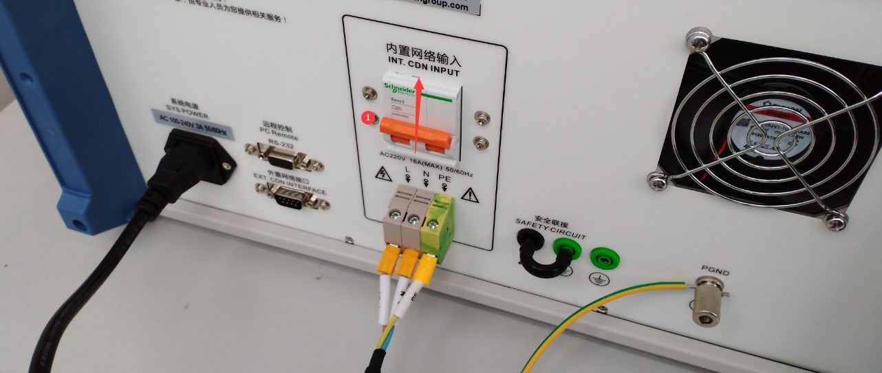
그림 5-1
Start the test; see Figure 5-2.
| 단계 | 주의 사항 |
| ① | Click “EUT Power” to power on the EUT |
| ② | Then click “Start” to begin the test. |
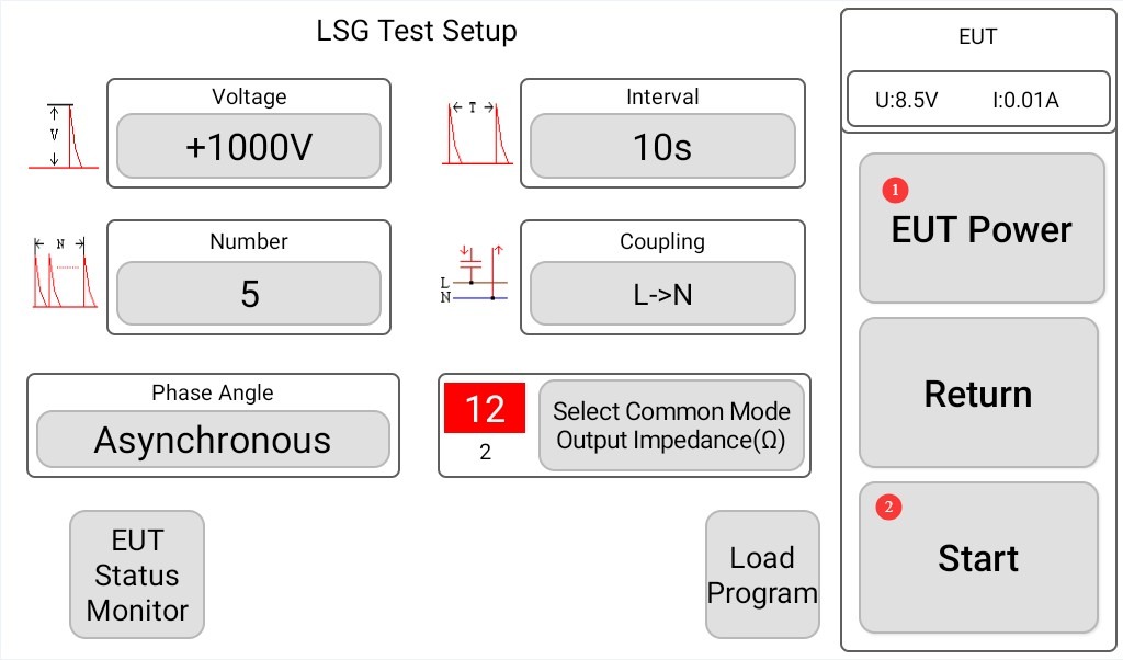
그림 5-2
If the oscilloscope function is checked, the program interface will display the surge voltage and current waveforms after each surge output, as shown in Figure 5-3:
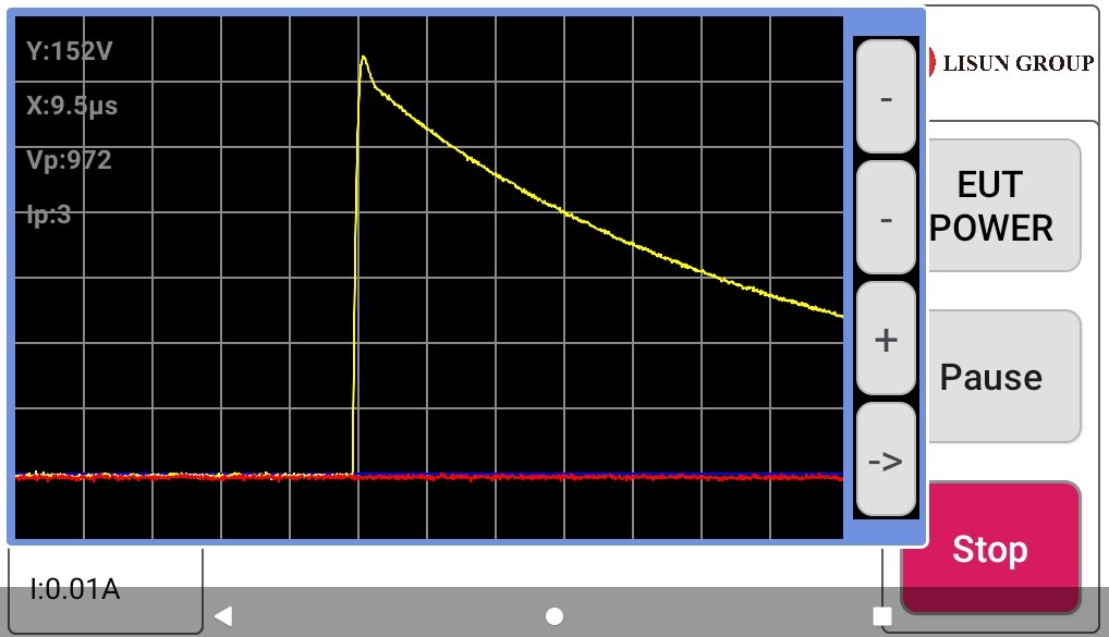
그림 5-3
Note: When the EUT is connected and testing is proceeding normally, the surge voltage and current values and waveforms will be affected. The surge voltage and voltage waveform (1.2/50 μs) specified in the standard must be measured under a fully open-circuit condition; the surge current and current waveform (8/20 μs) specified in the standard must be measured under a fully short-circuit condition.
Open circuit, meaning that no EUT or cable is connected to the CDN output terminal, as shown in Figure 5-4:
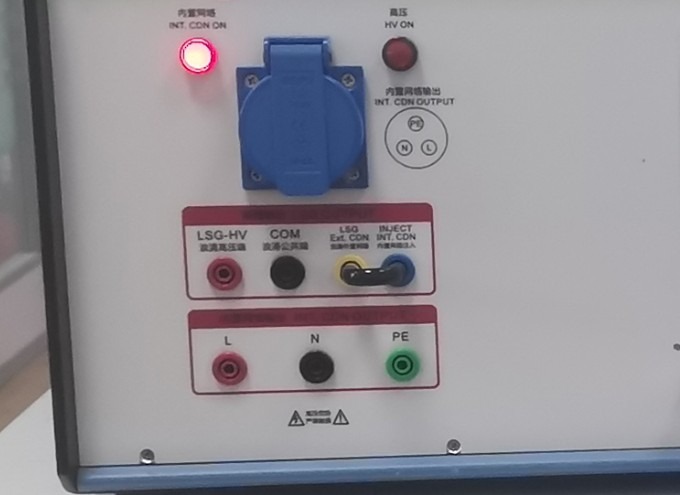
그림 5-4
For a complete short circuit, the two ends of the surge coupling direction must be short-circuited. For example, if the current coupling direction is set to L> N, the L and N terminals at the CDN output must be short-circuited, as shown in Figure 5-5;
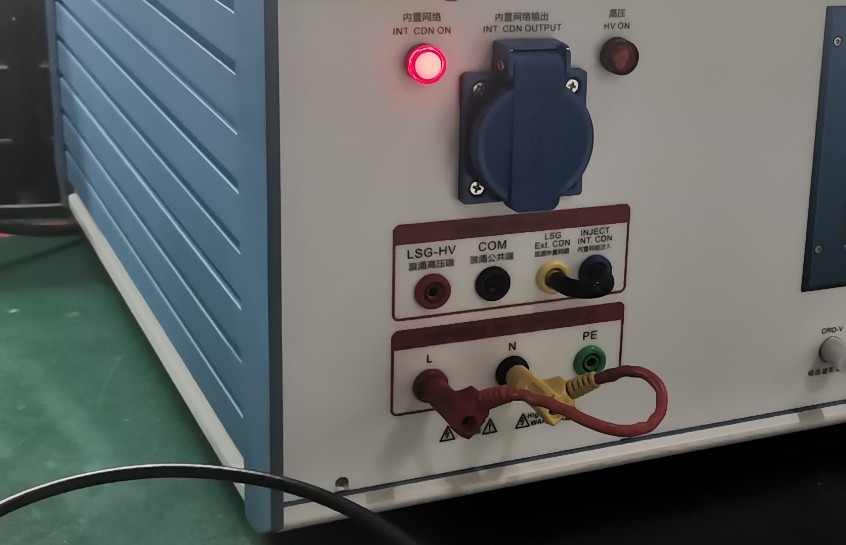
그림 5-5
5.2 Determining Whether the EUT Has Passed the Test
| 레벨 | 평가 기준 | Passed or Failed | 전형적인 증상 |
| Grade A (Criterion A) | Performance is completely normal within the specified limits, with no abnormalities whatsoever. | Usually deemed to have passed | No downtime, resets, display errors, or data loss; key parameters are within acceptable limits. |
| Grade B (Criterion B) | Temporary loss or reduction in function or performance, but recovery occurs automatically once the disturbance ceases, without the need for operator intervention | Must be arranged in advance; generally acceptable | Automatically resumes after a brief communication interruption; returns to normal after the screen flickers; returns to normal after a brief deviation from parameters |
| Class C (Criterion C) | Temporary loss or reduction in functionality or performance that requires manual intervention to restore (e.g., restart, reset) | Must be arranged in advance; acceptable in certain situations | If the equipment freezes, it must be manually restarted; if a program crashes, it must be reloaded; if parameters are out of range, they must be adjusted manually. |
| Grade D (Criterion D) | Irreversible loss of functionality or reduced performance due to hardware/software damage or data loss | Determined to be a failure | Components burned out, circuit boards damaged, stored data permanently lost, core functions irrecoverable |
5.3 Post-Test Procedures
5.3.1 Equipment Shutdown
If the EUT is visibly damaged during the test, immediately tap “Stop Test” on the touchscreen and tap “EUT Power” to turn off the EUT’s power.
If no abnormalities occur during the test, wait for the surge test to end automatically, then click “EUT Power” to turn off the EUT’s power.
Turn off the circuit breaker for the host’s built-in network CDN.
Wait 5 minutes to ensure that the high-voltage capacitors inside the main unit have fully discharged, then replace the EUT for testing, or turn off the power to the main unit and the Isolation Transformer.
5.3.2 Tidying Up and Cleaning
Clean the test area and wipe it down with a dry cloth. Do not use alcohol or corrosive cleaning agents.
Surge testing is a destructive test; it does not automatically generate a test report, but the device automatically saves the test data. You can go to “System Information,” click “Test Log,” and export the corresponding test data to a USB flash drive via the USB port. The exported file is in TXT text format, as shown in Figures 5-6.
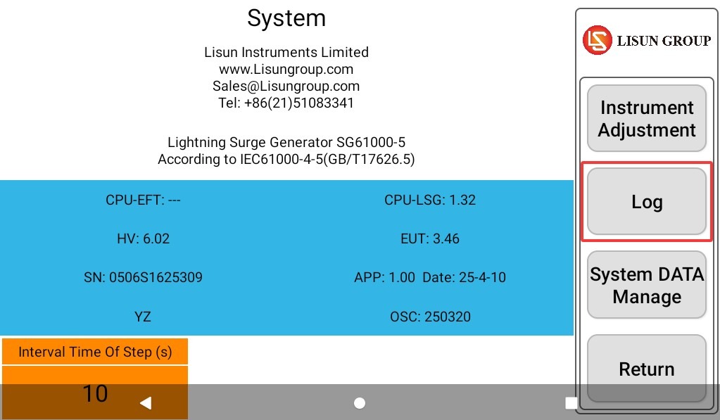
그림 5~6
6. 정기 유지보수 및 관리
6.1 장비 보관
6.1.1 Short-Term Storage Requirements
If the equipment is used on a daily basis, no further action is required after each test is completed and the equipment has been cleaned.
6.1.2 장기 보관 요건
기기를 장기간(한 달 이상) 사용하지 않을 경우 모든 케이블을 분리하고 먼지가 쌓이는 것을 방지하기 위해 먼지 덮개로 기기를 덮어주십시오.
전기 부품(콘덴서 및 접촉기 등)의 노화를 방지하기 위해 한 달에 한 번 기기를 켜고 30분 동안 켜둔 상태로 두어야 합니다.
6.2 교정 주기 요구사항
기기의 측정 정확도와 작동 신뢰성을 보장하기 위해, 자격을 갖춘 제3자 계측 연구소에 정기적으로 보내 교정을 받는 것이 좋습니다. 권장 교정 주기는 12개월입니다. 사용자는 사용 빈도, 환경 조건 및 품질 시스템 요구 사항을 고려하여 구체적인 교정 주기를 결정할 수 있습니다.
7. Use an external device to verify the surge output
7.1 Using an External Oscilloscope (Using the LISUN OSP Series Oscilloscope as an Example)
7.1.1 Using the CRO Port
7.1.1.1 Viewing Surge Voltage Waveforms
Set the following parameters for the Surge Generator: Set the surge voltage to +1 kV, set the coupling direction to L to N, set the interval as short as possible (e.g., 5 seconds), and set the number of surges to a higher value to make it easier to view each waveform.
Do not connect any EUT; ensure that the circuit is completely open. Then, use the coaxial cable provided to connect the lightning surge tester’s ① “CRO-V” port to the ② oscilloscope, as shown in Figure 7-1.
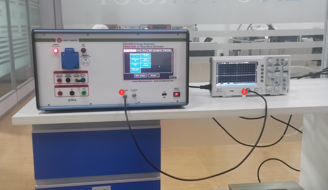
그림 7-1
Press the ① “Menu” button below the ② “Trigger” button, as shown in Figure 7-2.
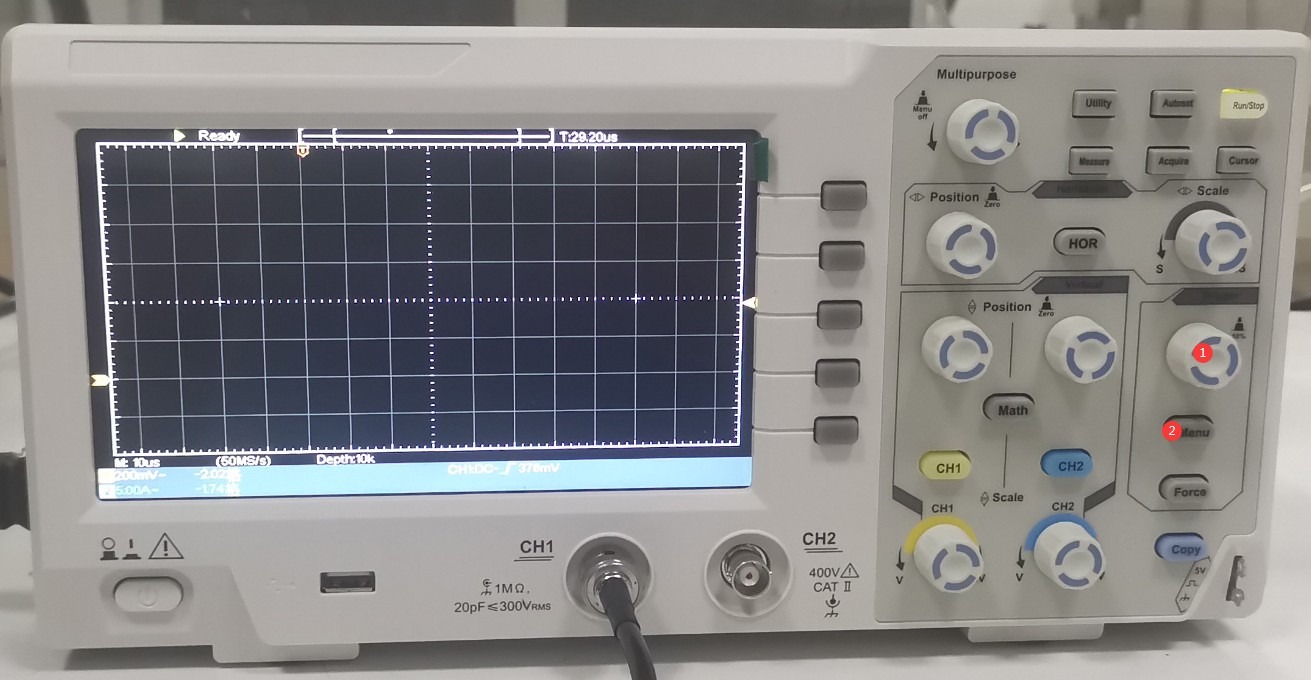
그림 7-2
See Figure 7-3: ① Select the connected channel; ② Set the trigger mode to “Normal”; ③ Click to proceed to the next page.
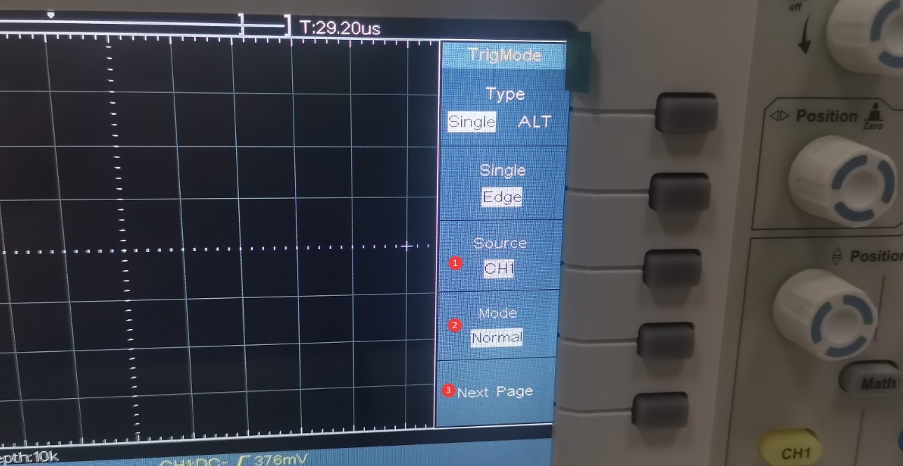
그림 7-3
See Figure 7-4; ① Select the rising edge.
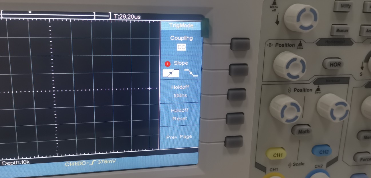
그림 7-4
As shown in Figure 7-5, press the ① CH1 knob.
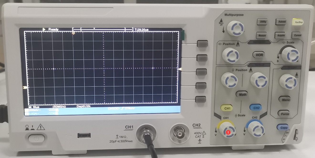
그림 7-5
See Figure 7-6: ① Select the 1X range; ② Turn off the current test function.
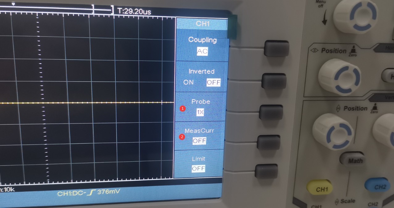
그림 7-6
The SG61000-5 series surge generator has a built-in 1000:1 Voltage Probe at the CRO interface. If the surge voltage is set to +1 kV, the actual voltage applied to the oscilloscope is 1 V. Refer to Figure 7-7. Turn the ① CH1 knob to set the ② oscilloscope’s vertical scale to 1/5 per division, or 200 mV, which makes it easier to view the entire waveform. Turn the ③ “Scale” knob to set the ④ oscilloscope’s horizontal time scale to 10 µs per division.
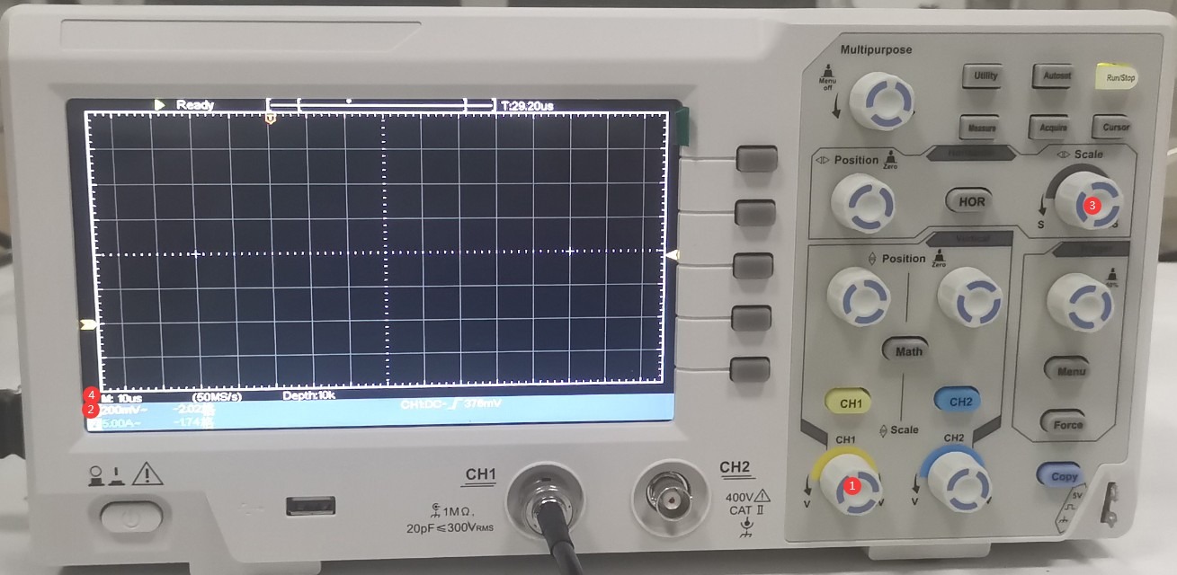
그림 7-7
Refer to Figures 7–8. Turn knobs ① (left/right) and ② (up/down) to adjust the waveform display to the appropriate position shown in the figure. Turn knob ③ (“Trigger”) to adjust the level to approximately the middle position.
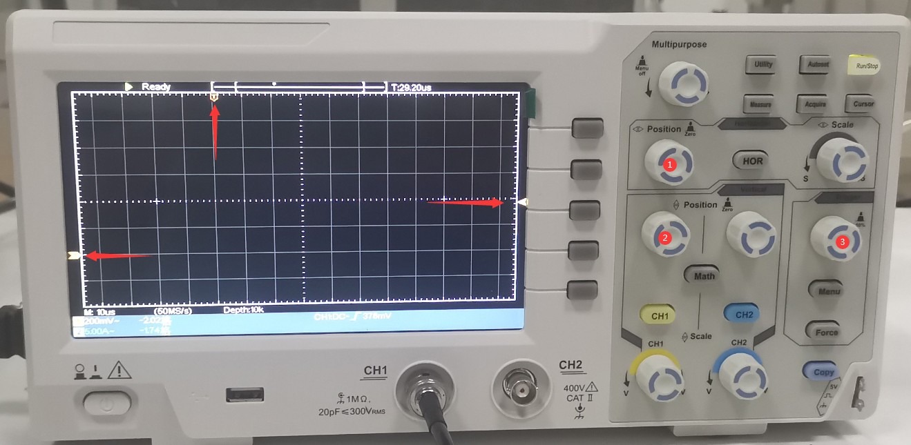
그림 7~8
For the lightning surge test on the touchscreen, do not click “EUT Power”; instead, click “Start” directly. As shown in Figures 7–9, each time a surge is output, the oscilloscope will capture a surge voltage waveform as illustrated below. Use the horizontal cursor to verify the surge output voltage. Since the Surge Generator is set to 1 kV, the oscilloscope should display a reading of 1 V.
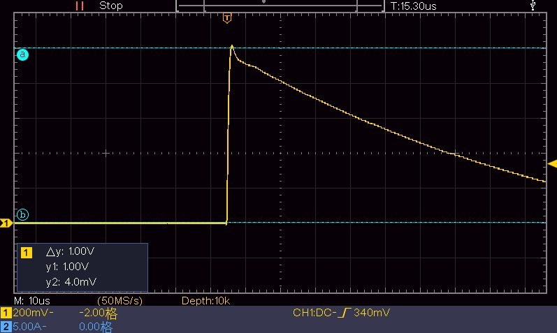
그림 7~9
Use the vertical cursor to confirm the surge half-width time; see Figure 7-10.
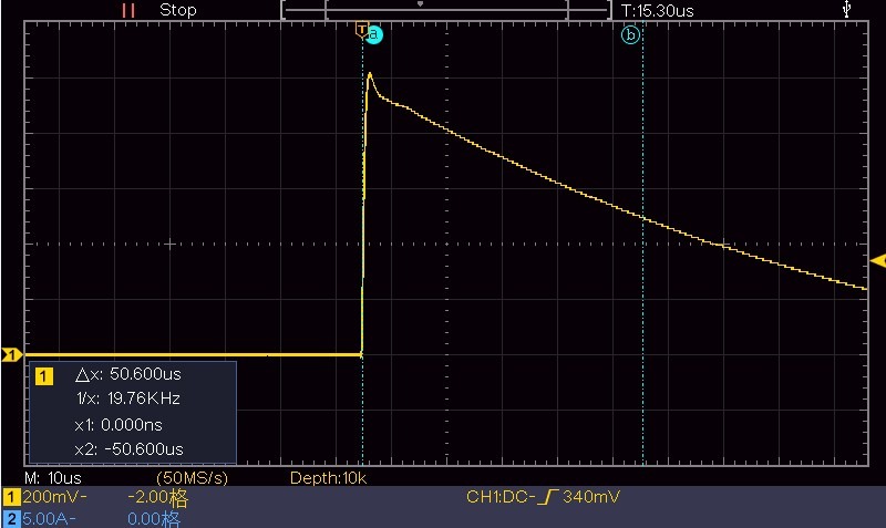
그림 7~10
Set the time base to 1 µs, leaving all other settings unchanged. Wait for the next surge output, then use the vertical cursor to determine the rise time of the surge, as shown in Figure 7-11.
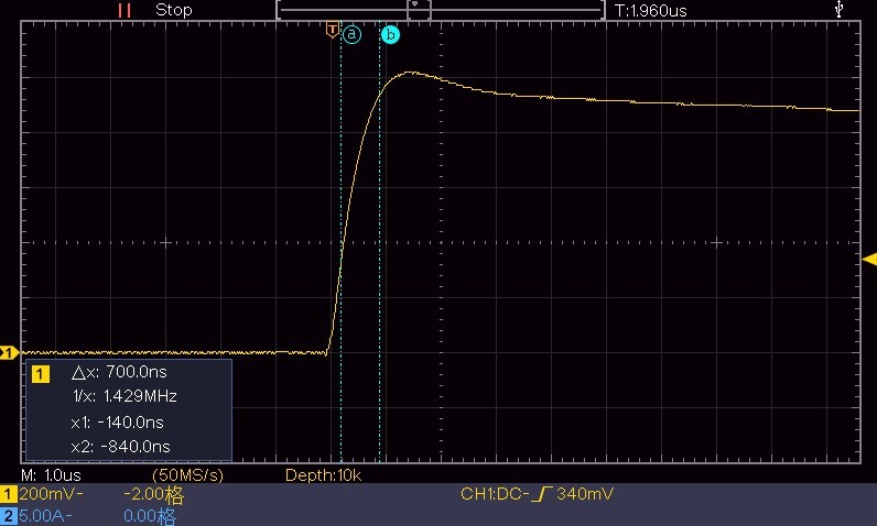
그림 7-11
7.1.1.2 Viewing the Surge Current Waveform
Keep the Surge Generator settings unchanged. ① Connect the coaxial cable to the “CRO-I” port to prepare for monitoring the surge current waveform. ② Short-circuit L and N to ensure a complete short-circuit condition. See Figure 7-12.
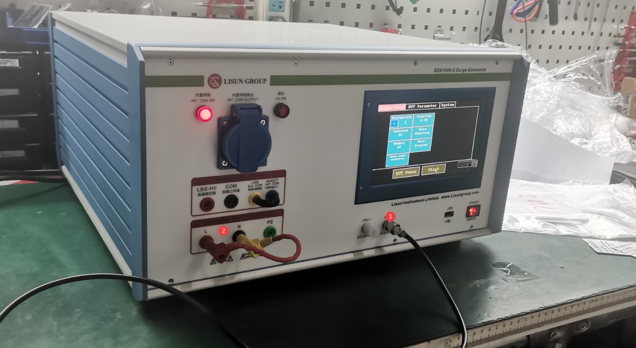
그림 7-12
The impedance between L and N in differential mode is 2 Ω, so the vertical scale of the oscilloscope is set to 1/2/5 = 100 mV. The horizontal scale is set to 5 μs. The other settings are the same as when viewing voltage waveforms. The same procedure is used to measure the output surge. The oscilloscope displays the waveform shown in Figure 7-13.
Note: Here, the current is determined using the method for measuring voltage. The actual current is 1000 V / 1000 / 2 Ω = 500 mA, which corresponds to the 500 mV shown in the figure below.
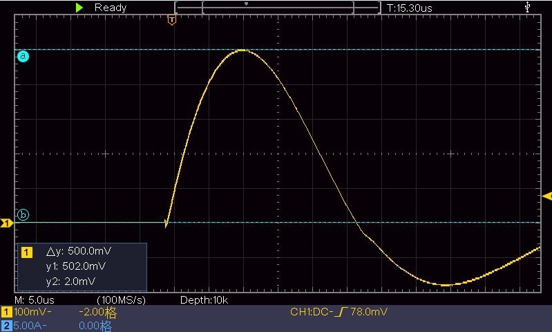
그림 7-13
To view the half-width, see Figure 7-14.
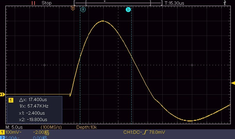
그림 7-14
See Figure 7-15 for the leading edge time.
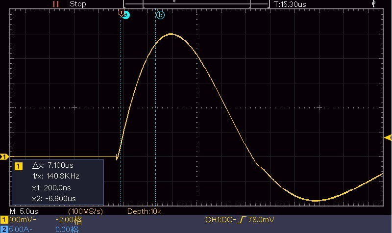
그림 7-15
7.1.2 Using the CDN Output Port
The built-in digital oscilloscope and CRO port are both provided to make it easier for users to view waveforms. However, if you need to calibrate the device, you must provide your own high-voltage probe and connect the oscilloscope directly to the CDN output port on the front panel of the surge generator. Refer to Section 7.1.1 and the scale of the high-voltage probe you are using when operating the oscilloscope.
7.2 Using a Discharge Tube
A discharge tube can be used to easily verify whether a device produces a surge.
Connect the discharge tube to the Surge Generator as the EUT. For the Surge Generator’s program interface settings and discharge tube connection, refer to Figure 7-16:
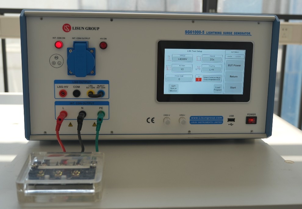
그림 7-16
Do not click to turn on “EUT Power”; instead, click “Start” directly to begin the surge test. See Figure 7-17:
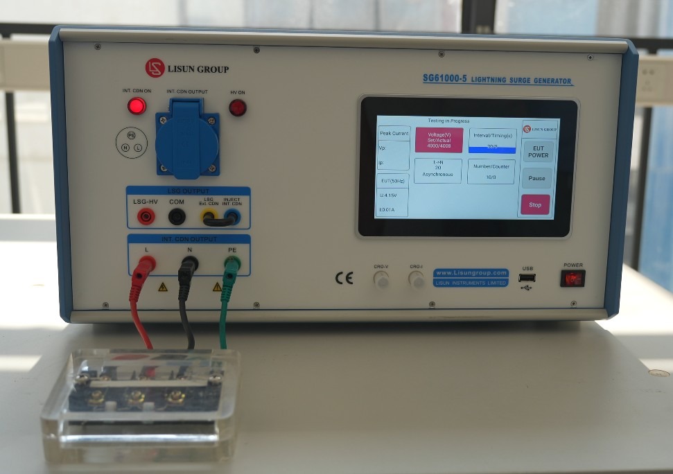
그림 7-17
When the surge is output, the discharge tube will flash; please dim the lights in the room to make it easier to observe. See Figure 7-18:
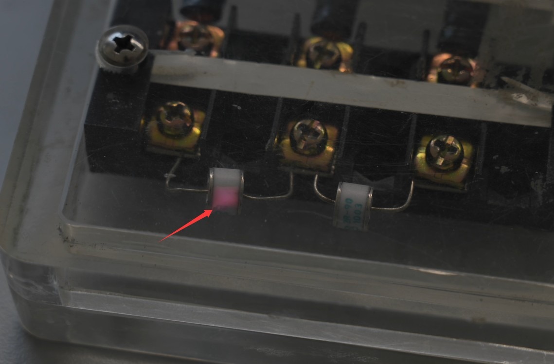
그림 7-18
This indicates that the device is indeed producing an output surge. If the discharge tube does not flash, please contact customer service.
8. 문제 해결 및 일반적인 문제 해결 방법
8.1 기기가 켜지지 않습니다
Symptom: After turning on the power switch, the device does not respond (the indicator light does not come on, and the fan does not spin).
Possible causes: ① The power cord is not properly connected or is damaged; ② Abnormal supply voltage; ③ A blown fuse; ④ A burned-out varistor (MOV).
Troubleshooting: Ensure the power cord is intact and securely connected. Power supply issues—such as unstable voltage, excessively high voltage, or harmonic interference—can cause the fuse or varistor to blow. It is recommended to use a voltage-stabilized, clean sine-wave AC power supply to power the device. Replace the fuse or varistor with one of the same type.
For the fuse locations, see Figure 8-1:
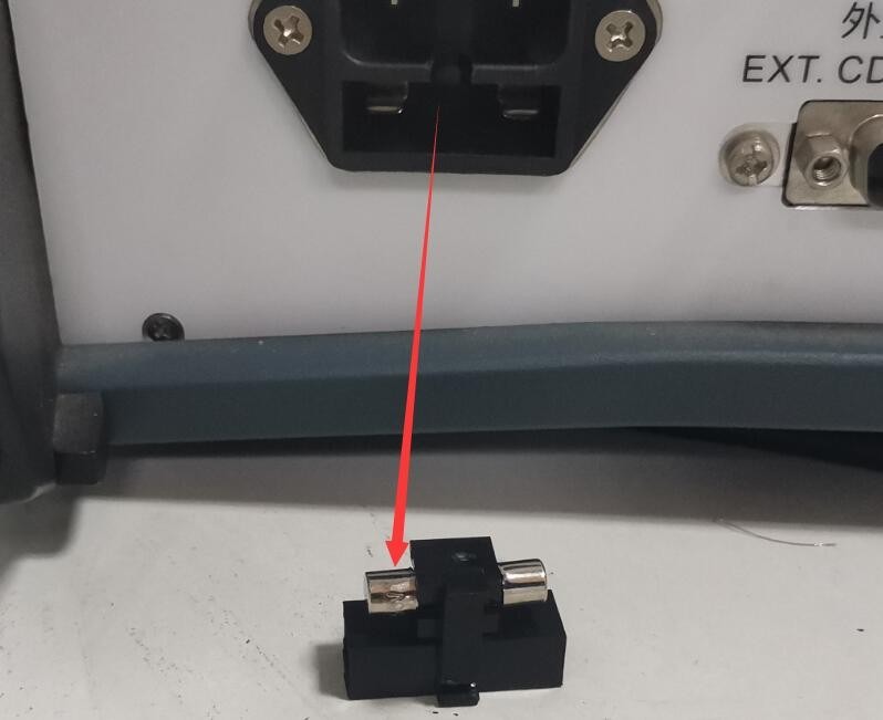
그림 8-1
See Figure 8-2 for the location of the MOV (metal-oxide varistor) inside the filtered power supply:
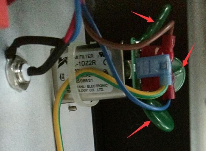
그림 8-2
8.2 Circuit Breaker Trip in the Laboratory
Symptom: When a surge is output, the laboratory ground-fault circuit interrupter trips.
Possible cause: The Isolation Transformer is not connected.
Procedure: Connect the Isolation Transformer as described in Section 3.1. Surge testing generates large instantaneous pulse currents; if an Isolation Transformer is not connected, it may cause the laboratory’s ground-fault circuit interrupter to trip.
8.3 Automatic Device Restart
Symptom: The device automatically restarts when a surge occurs.
Possible cause: The ground wire is not connected properly.
Solution: Refer to Section 3.1. Connect the PGND grounding terminal on the back of the host to ground, and ensure that the grounding resistance is ≤4Ω; otherwise, high voltage may not be safely dissipated, causing the device to automatically restart.
8.4 Surge Phase Angle Test Failed
Symptom: The synchronization phase angle was set, but the surge test was not performed according to the corresponding phase angle.
Possible cause: The EUT power is not turned on.
Procedure: The EUT must be powered by an AC source, and it must be turned on during testing so that the surge generator can detect the EUT’s power waveform and perform the surge test according to the set phase angle.
8.5 The waveform contains interference.
Symptom: When using the built-in digital oscilloscope or the CRO port to examine a standard surge waveform, zooming in on the waveform reveals some noise. See Figures 8-3 and 8-4:
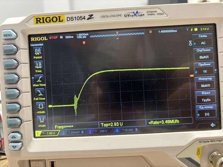
그림 8-3
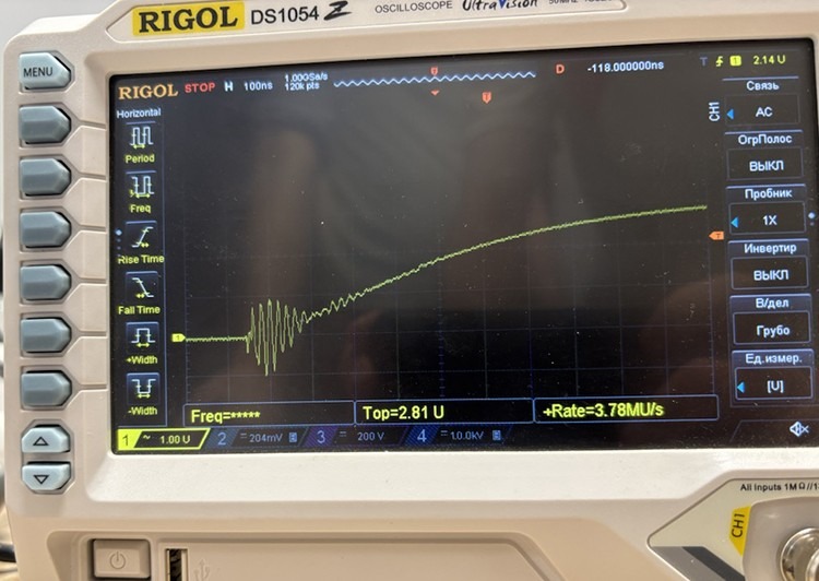
그림 8-4
Possible cause: The built-in digital oscilloscope and CRO port are intended to make it convenient for users to quickly and easily obtain waveform data, but they may generate a small amount of noise.
Procedure: If you need to obtain the actual output waveform of the surge generator, or if you wish to calibrate the device, use an oscilloscope and a high-voltage probe to directly inspect the waveform at the CDN output terminal, as shown in Figures 8-5 and 8-6:
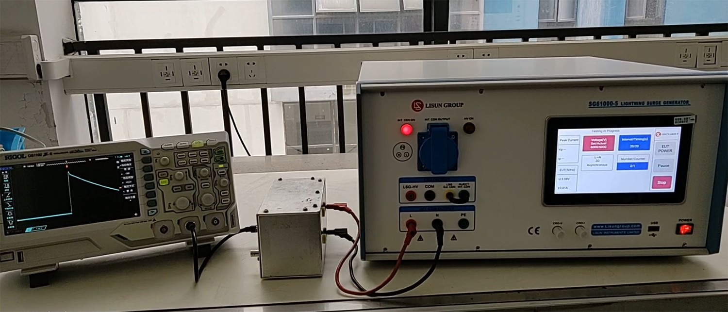
그림 8-5
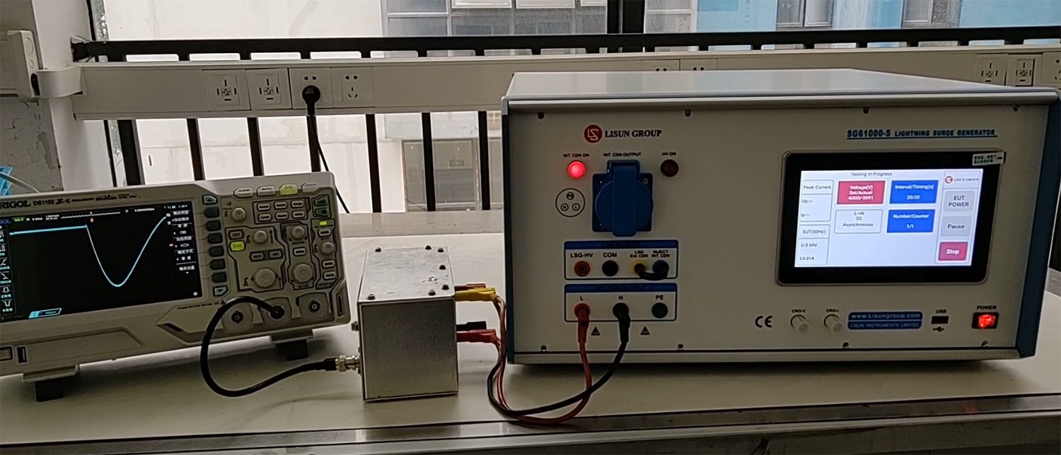
그림 8-6