
 영어
영어 中文简体
中文简体 Русский
 Español
 Português
 Türkçe
 العربية
 Deutsch
 Polski
 Italiano
 Français
 한국어
한국어 ไทย
ไทย Tiếng Việt
 日本語
日本語





























테스트 핑거
사용자 설명서
적용 할 수있는 LISUN 모델: SMT-1211,SMT-PB
1. “Test” refers to Basic understanding.
1.1 적용 가능한 표준
This series of tests refers to those conducted in strict accordance with GB/T 42125.1-2024″Safety Requirements for Electrical Equipment for Measurement, Control, and Laboratory Use—Part 1: General Requirements” (equivalent to IEC 61010-1:2016), and are applicable to safety testing of the accessibility of various types of measuring instruments, control equipment, laboratory analytical equipment, industrial automation instruments, and other products. It may also be used for safety certification testing of products under the same standards system.
SMT-PB: Fully complies with the specifications for the articulated Test Finger in GB/T 42125.1-2024, Figure B.2 (IEC 61010-1:2016, Figure B.2).
SMT-1211: Fully complies with the specifications for the rigidity test as shown in Figure B.1 of GB/T 42125.1-2024 (IEC 61010-1:2016 Figure B.1).
1.2가지 핵심 기능
The SMT-PB articulated Test Finger and the SMT-1211 rigid Test Finger are specialized instruments for measuring, controlling, and conducting safety inspections of electrical equipment in laboratories. They are used to simulate a human finger inserted into an opening in the equipment enclosure to verify whether dangerous live parts inside the equipment, dangerous mechanical parts within the equipment can be reached by a normally operating person, thereby determining whether the equipment’s protection rating against electric shock and mechanical injury complies with standard requirements.
1.3 Explanation of the Test Principle
1.3.1 Principles for Determining Accessibility
By applying the Test Finger with a specified force to various openings in the equipment enclosure (such as ventilation holes, seams, slots, and adjustment holes), if the metal-detecting portion of the Test Finger comes into contact with internal hazardous live parts or hazardous moving parts, the equipment is deemed to fail the protection test; if it does not come into contact, the protection is deemed effective.
1.3.2 Division of Labor Between the Two Test Fingers
The SMT-PB articulated Test Finger simulates the natural bending motion of human finger joints. It is primarily used for accessibility testing of standard openings and can reach deep into gaps while adjusting its angle for inspection.
SMT-1211 Rigid Test Finger: If the hinged Test Finger passes the test but there is suspicion that the enclosure opening may deform under the standard 10 N external force, thereby exposing internal hazardous parts, a rigid Test Finger must be used to apply the specified thrust for supplementary verification.
1.4 전자 문서 다운로드
전자 사용자 설명서, 교정 인증서, 보증서 및 기타 문서의 다운로드 링크는 제품 발송 시 이메일로 이미 보내드렸습니다. 가능한 한 빨리 다운로드해 주시기 바랍니다. 만약 이메일을 받지 못하셨다면, 저희에게 연락하여 다운로드 링크를 다시 요청해 주십시오.
2. 안전상의 주의
2.1 Test Environment Requirements
2.1.1 환경 조건
Tests should be conducted under normal temperature and humidity conditions, with an ambient temperature of 15°C to 35°C and a relative humidity of 25% to 75%. Live testing is prohibited in environments containing flammable or explosive gases to prevent safety incidents.
2.1.2 Workbench Requirements
시험 대상 장치는 견고하고 평평하며 절연된 작업대 위에 놓아야 하며 시험 중에는 이동해서는 안 됩니다. 또한 시험 중 다른 활선 장비와의 접촉을 방지하기 위해 작업대 주변에 충분한 작업 공간을 확보해야 합니다.
2.3 운영 안전 지침
2.3.2 기계 작동 시 안전
Apply force slowly and evenly; do not apply sudden force or pry on the equipment housing to avoid damaging the Test Finger or causing injuries from impact.
날카로운 모서리가 있는 장비를 테스트할 때는 장비 본체의 거친 부분으로 인한 베임을 방지하기 위해 보호 장갑을 착용하십시오.
Test Finger is a precision measuring instrument; do not strike, throw, or use it as a prying tool.
During the test, it is strictly prohibited to aim the test fixture at any part of the human body to prevent mechanical injury while applying force.
2.3.2 Electrical Safety of the Device Under Test
Unless otherwise specified by special live-line testing requirements, prior to routine protection-against-accidental-contact testing, the equipment under test must be disconnected from the main power source, and any energy-storage components, such as internal capacitors, must be fully discharged.
The test circuit supplies power to the live components under test only through a dedicated safety extra-low-voltage power source; connecting the equipment under test to the mains power supply for testing is prohibited.
2.4 Testing Refers To Safety Protection
Do not exceed the test force of 10 N specified in the standard to avoid damaging the device under test or causing permanent deformation of the Test Finger.
금속 부품의 부식 및 절연 손잡이의 열화를 방지하기 위해 강산이나 강알칼리와 같은 부식성 물질과의 접촉을 피하십시오.
3. Introduction to Test Fingers
3.1 Standard Diagram
3.1.1 SMT-PB Articulated Test Finger
See Figure 3-1 (taken from IEC 61010-1:2016, Figure B.2).
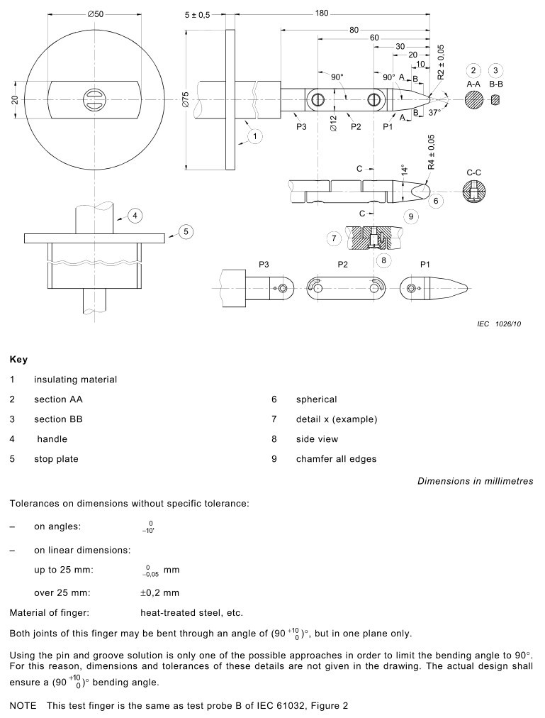
그림 3-1
3.2.2 SMT-1211 Rigidity Test Specification
See Figure 3-2 (taken from IEC 61010-1:2016, Figure B.1).
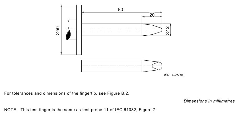
그림 3-2
3.2 실제 대상물의 사진
3.2.1 SMT-PB Articulated Test Finger
All are wired models; see Figure 3-3.
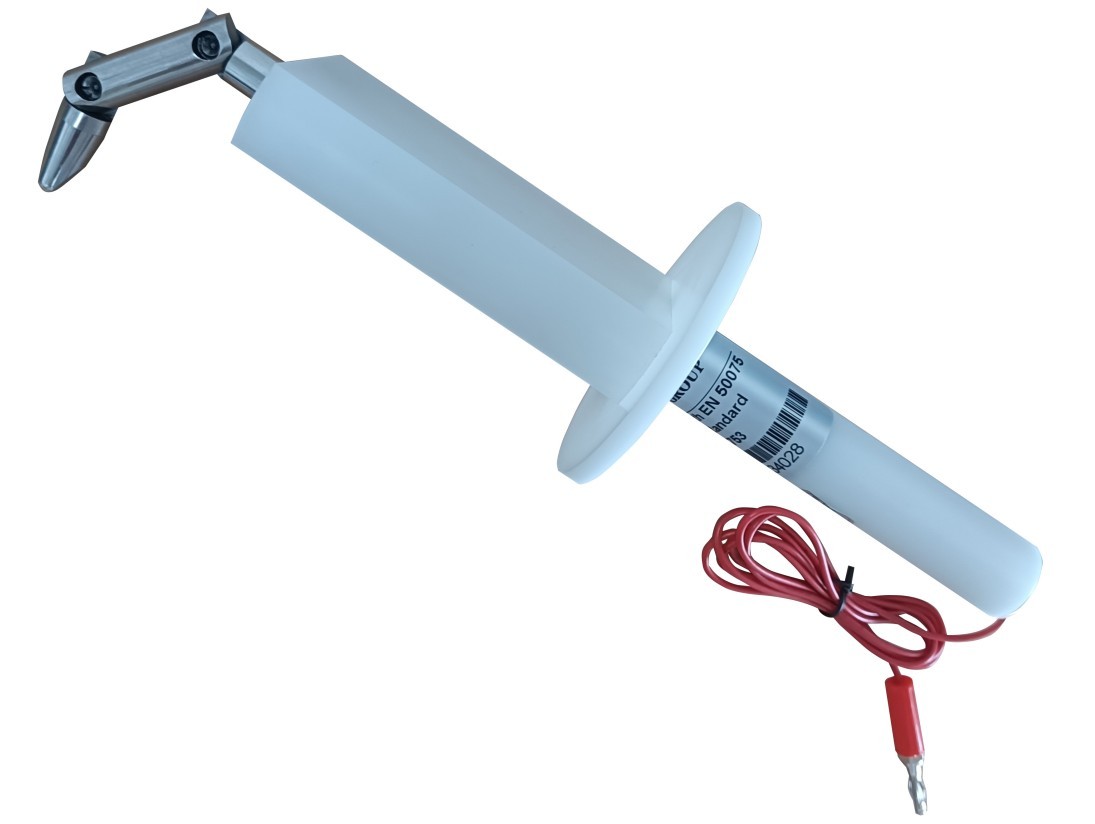
그림 3-3
3.2.1 SMT-1211 Rigidity Test Specification
그림 3~4을 참조하십시오.
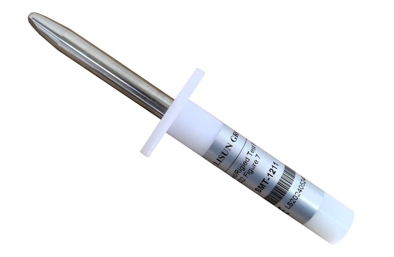
그림 3-4
3.3 Test Finger As an Auxiliary Function
3.3.1 전선 유무에 관계없이
SMT-PB refers to the main Test Finger; in the vast majority of scenarios, it is necessary to determine whether live parts are accessible, which requires the inclusion of terminal blocks.
The SMT-1211 is a supplementary verification Test Finger. Whether a wired version is required depends on the purpose of the test: If the test is solely to verify whether the mechanical opening can be breached or whether hazardous mechanical components can be reached, no wiring is necessary—a visual or structural assessment is sufficient; If the test is to verify whether hazardous live parts can be reached after deformation under load, a conductive rigid Test Finger must be used in conjunction with an alarm device to make the determination.
The SMT-1211 comes without cables by default. Users may choose between the wired or wireless version based on their needs.
3.3.2 Does it come with a thrust gauge?
LISUN tests indicate that some units come with a thrust gauge by default, while others do not.
If the user already has a thrust gauge that meets the specifications, they may choose the model without a built-in thrust gauge. You may specify whether to include a built-in thrust gauge based on your actual needs. Note: The price may vary depending on whether a thrust gauge is included.
4. 시험 전 준비 사항
4.1 보조 장비 준비
4.1.1 Push-Pull Force Gauge
시험 중 가해지는 힘을 정밀하게 제어하는 데 사용됩니다.
4.1.2 안전 초저전압 전원 공급 장치
A Test Finger is used to trigger audible and visual alarms when it comes into contact with live parts. The LISUN SMT-529CV can be used for this purpose; it provides a test voltage of 40–45 V to simulate contact by a finger, tool, or metal wire, and is compatible with all types of test fingers with wires. See Figure 4-1.
| 번호 | 주의 사항 |
| ① | Test Voltage Display |
| ② | Test voltage output, used to connect the test leads to the tail end of the Test Finger |
| ③ | 시험 전압 회로; 시험 대상 장치를 연결하는 데 사용되는 케이블 |
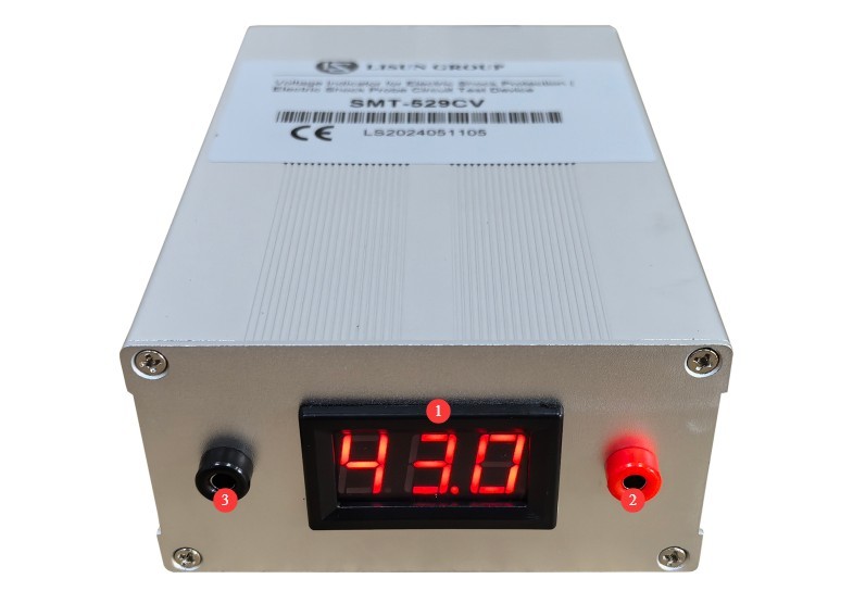
그림 4-1
4.2 시험 대상 기기의 준비
4.2.1 Verification of Equipment Status
Verify that the enclosure of the device under test is intact and free of damage.
In accordance with the standard requirements, the accessibility test must be conducted with the device powered off and de-energized.
All removable covers, knobs, fuse covers, and other components on the equipment should be properly installed in their normal operating positions.
4.2.2 Summary of Test Locations
Conduct a thorough inspection of all possible openings in the equipment housing, including: cooling grilles, panel seams, connector slots, adjustment holes, vents, installation gaps, and bottom openings.
5. “Test” Refers To the test procedure.
5.1 SMT-PB Articulated Test Finger Procedure
5.1.1 Connections Before Testing
4.1.2를 참조하십시오.
Connect the terminal block at the rear of the SMT-PB to the output of the safety extra-low-voltage power supply (SMT-529CV).
Connect the cable of the device under test to the input terminal of the safety extra-low-voltage power supply (SMT-529CV).
Turn on the alarm tester, perform a short-circuit self-test, and verify that the audible and visual alarms are functioning properly.
5.1.2 Point-by-Point Testing Procedures
Hold the insulated handle and align the tip of your Test Finger with the center of the opening being tested.
Move forward slowly while adjusting the angle at which you bend your fingers to match the internal structure of the opening, trying to reach as deep into the crevice as possible.
Stop advancing when the baffle comes into contact with the surface of the equipment housing or encounters noticeable resistance.
Apply a constant thrust of 10 N along the axis and maintain it for at least 3 seconds.
Check the status of the alarm tester: If an audible and visual alarm is triggered, it indicates that the Test Finger has come into contact with a hazardous live part, and that test point fails the test; if no alarm is triggered, it indicates that the Test Finger has not come into contact with any live parts.
While maintaining pressure, gently move the Test Finger up, down, left, and right within a small range to simulate a finger probe and confirm once again whether the hazardous component can be felt.
5.2 SMT-1211 Rigidity Test: Operating Procedures
5.2.1 Confirmation of Applicable Scenarios
If, after testing with an articulated Test Finger, there is concern that the enclosure opening may deform under load, causing internal components to become accessible, perform a verification test using a rigid Test Finger. Connect or disconnect the electric shock alarm tester (SMT-529CV) as needed.
5.2.2 시험 절차
Align the tip of the rigid Test Finger with the opening being tested, keeping the Test Finger perpendicular to the plane of the opening.
Slowly apply axial thrust, gradually increasing the force to 10 N.
While maintaining a constant axial thrust of 10 N, gently swing the Test Finger slightly from side to side and up and down to thoroughly inspect all areas inside the opening and confirm that no hazardous components are within reach.
During testing, prying or wedging actions are prohibited; only positive pressure applied along the axial direction is permitted.
If the Test Finger can pass through the opening and come into contact with the hazardous part, the guarding at that location is deemed noncompliant; otherwise, it is compliant.
5.3 Test Evaluation Criteria
5.3.1 Conformity Assessment
A test point is deemed to meet accessibility protection requirements if all of the following conditions are met: When a Test Finger is applied with the specified force, the metal detection component cannot come into contact with hazardous live parts; the Test Finger cannot come into contact with hazardous moving parts, sharp parts, or other mechanically hazardous areas; and the limit stop cannot pass through the opening into the interior of the equipment.
5.3.2 Determination of Nonconformity
If any of the following conditions occurs, the protection at that location shall be deemed non-compliant: the Test Finger comes into contact with a hazardous live part, triggering the alarm; the Test Finger can reach a hazardous mechanical part that is moving at high speed and has sharp edges; the guard can pass through the opening, allowing the Test Finger to penetrate unimpeded into the interior of the equipment.
6. Testing Refers To routine maintenance and servicing
6.1 일상 청소 및 유지 관리
깨끗하고 부드러운 천으로 테스트 핑거 표면의 먼지나 기름기를 닦아내십시오.
Gently wipe the metal parts with anhydrous ethanol to remove stains and fingerprints.
절연 손잡이는 순한 세제로 닦고 완전히 말리십시오. 강한 용제를 사용하여 세척하지 마십시오.
부드러운 솔을 사용하여 이음새 틈새의 먼지를 제거하고, 부품이 원활하게 움직이도록 소량의 중성 윤활 그리스를 바르십시오.
6.2 장기 보관 및 유지 관리
정기적인 청소 및 유지 보수를 마친 후 금속 표면에 녹 방지 오일을 얇게 바르고, 녹 방지용 종이로 감싼 다음, 먼지 덮개를 씌워 건조하고 통풍이 잘 되는 창고에 보관하십시오.
The test fixtures must be stored in their designated storage boxes to avoid crushing or impact and prevent deformation.
6.3 교정 주기 요구사항
기기의 정확성과 신뢰성을 보장하기 위해, 공인된 제3자 계측 연구소에 정기적으로 보내 교정을 받는 것이 좋습니다. 권장 교정 주기는 12개월입니다. 사용자는 사용 빈도, 환경 조건 및 품질 시스템 요구 사항을 고려하여 구체적인 교정 주기를 결정할 수 있습니다.
7. 문제 해결 및 일반적인 문제 해결 방법
| 결함 증상 | 가능한 원인들 | 순서 |
| 관절 강성 | Dust enters the joint space | 접합부 틈새를 무수 에탄올로 깨끗이 닦고 자연 건조시킨 후 중성 윤활 그리스를 바르십시오. |
| Poor electrical conductivity; abnormal results in electric shock protection testing | 오래되었거나 헐거워진 케이블 | Use a multimeter to measure the resistance between the Test Finger of the test probe and the terminal at the end of the cable. If the resistance is greater than 1 Ω, it will affect the test results; check the wiring or return the unit to the factory for repair. |