
 영어
영어 中文简体
中文简体 Русский
 Español
 Português
 Türkçe
 العربية
 Deutsch
 Polski
 Italiano
 Français
 한국어
한국어 ไทย
ไทย Tiếng Việt
 日本語
日本語





























습식 이산화탄소-이산화황-공기 시험 챔버
사용자 설명서
적용 할 수있는 LISUN models: SQCO-300
1 Safety Instructions (Precautions)
Thank you very much for purchasing our company’s constant temperature and humidity programmable controller.
This user manual describes how to operate this product as follows.
| Precautions in This User Manual |
(A) Please provide this operating manual to the end user and keep it in a place where it can be easily accessed at any time.
(B) Please read this user manual carefully before using this product.
(C) This user manual provides a detailed description of the product’s various functions; no warranty is provided for matters not covered in this user manual.
(D) No part of this operating manual may be edited, copied, or used without permission.
(E) The contents of this operating manual are subject to change without prior notice or announcement.
(F) Although every effort has been made to ensure the completeness of this user manual, there may still be some imperfections, typographical errors, or omissions. If you find any such issues, please contact the place of purchase or our company. Thank you very much.
| Safety and Modification (Change) Precautions for This Product |
(A) To ensure the maintenance and safety of this product and the systems connected to it, please be sure to carefully read the safety precautions (instructions) in this user manual before using this product.
(B) The Company assumes no liability for any losses resulting from failure to use or store the product in accordance with the instructions in this manual, or from negligence.
(C) To ensure the maintenance and safety of this product and the systems connected to it, if it is necessary to install additional protective devices or safety circuits, be sure to install them on the exterior of this product. Modifications (changes) or additions to the interior of this product are strictly prohibited.
(D) Please do not disassemble, repair, or modify this product without authorization, as doing so may result in electric shock, fire, or malfunction.
(E) Be sure to contact our Sales Department when replacing parts or consumables for this product.
(F) Please do not allow moisture to enter this product, as it may cause a malfunction.
(G) Please do not drop or strike this product, as this may cause damage or malfunction.
| Disclaimer for This Product |
(A) Except as set forth in the Company’s warranty terms, the Company makes no warranties and assumes no liability.
(B) The Company shall not be liable for any direct or indirect damages incurred by the user or a third party arising from defects unforeseeable by the Company or from natural disasters during the use of this product.
2 Operation and Settings
2.1 Basic Operational Flowchart
▶ After initially installing the product, plug it in, and the startup progress screen will appear.
☞ The startup screen takes about 15 seconds to load.

시작 화면
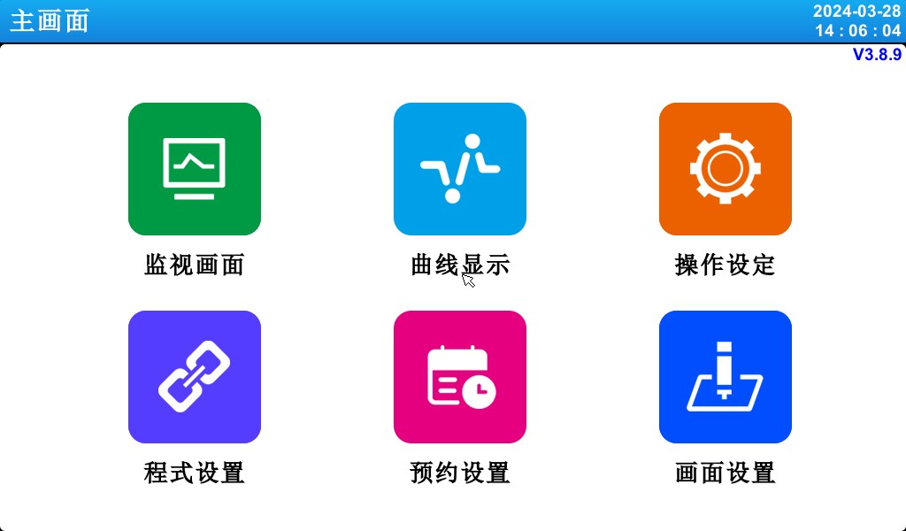
메인 화면
2.2 How To Set Parameters (PARAMETER)
Field for Numeric Input Only
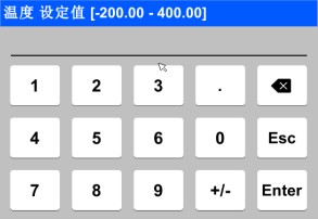
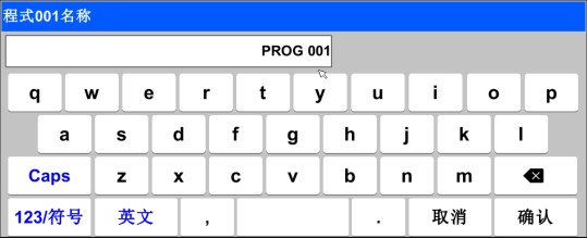
Input fields for setting the experiment name and the DI fault name
| Touchscreen Lock (KEY LOCK) Unlock ▶ You cannot enter settings while the “Lock” status is set to “ON (Locked),” so be sure to change the “Lock” status to “OFF (Unlocked)” before entering any values. ☞ For detailed setup instructions, refer to [4. Operation Settings]. |
2.2.1 Validity of Setting Keys and Setting Values
▶ This product emits the following beeps to confirm that the set value input key has been pressed and to verify that the entered set value is valid.
☞ “Bi”: When you press the Basic Settings button and the entered value is correct
☞ “BBB”: When the value entered in the input field is outside the valid range
| Operating Precautions ▶ When pressing the Basic Settings button or the setting value input field, do not use sharp objects (such as pencils) or tap too hard. Doing so may cause the device to malfunction or damage the touchscreen. |
2.2.2 Methods for Entering Setpoints
▶ Features and Description of the Set Value Input Field


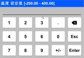
① Display “Parameter (PARAMETER).”
② Displays “Setting Range.”
③ is the “Setpoint Display Window,” which displays a fault alert (“Input Error”) when the value exceeds the set range.
④ Use this key to stop typing and return to the previous screen.
⑤ After saving the input value, return to the previous screen.
⑥ Use this when entering a decimal point.
⑦ Use this when entering the (+/-) sign.
⑧ Use this when editing an input value; you can delete characters one by one.
3. Operating Mode Settings

3.1 메인 화면


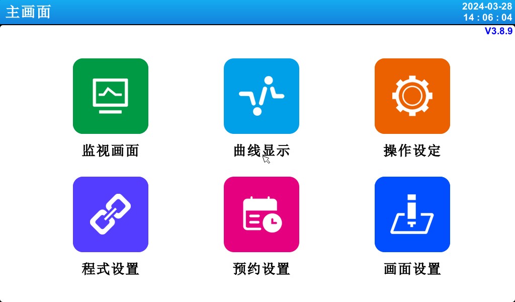

[Figure 3-1] Main Screen
| 번호 | 명령 | 내용 설명 |
| ① | 감시 영상 | Switch to the Run screen. |
| ② | 곡선형 디스플레이 | Switch to curve display and curve storage, USB storage devices, and curve export. |
| ③ | 작동 설정 | Switch to the settings screen for functions and operating modes. |
| ④ | 프로그램 설정 | Switch to the main settings screen. |
| ⑤ | 예약 설정 | Switch to the screen for setting the current time and the scheduled time. |
| ⑥ | 디스플레이 설정 | Use the prompt tone to display the settings screen. |
3.2 FIX Mode Operation
3.2.1 Fixed-Value (FIX) Operation: Stop Screen 1
▶ Select the monitoring screen in [3.1 Main Screen] to switch to the “Fixed-Value (FIX) Operation, Screen 1.”
▶ In [4. Operation Settings], select “Fixed Value (FIX)” as the operating mode.
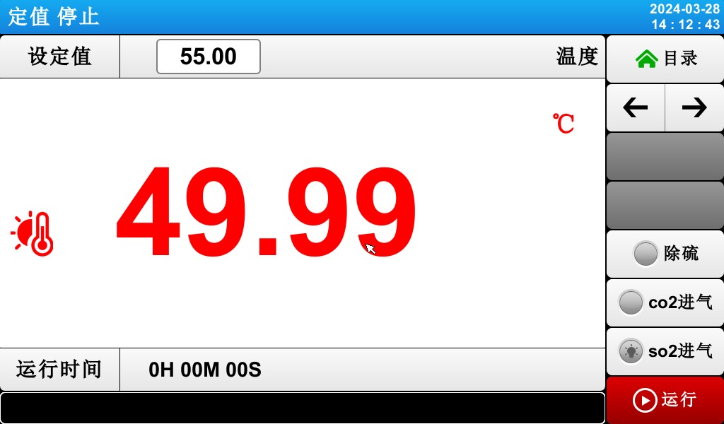
[Figure 3-2] Fixed-Value (FIX) Operation: Stop Screen 1
▶The methods for entering temperature setpoints and operating the system are as follows.
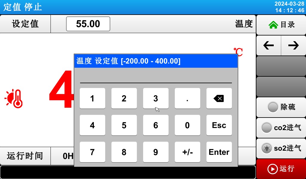
[Figure 3-3] Temperature Setpoint Input Field
▶ When entering a temperature setpoint, tap the red button in the upper-left corner to activate the temperature setpoint input field shown in [Figure 3-3: Temperature Setpoint Input Field].
3.2.2 Fixed-Value (FIX) Operation: Screen 1


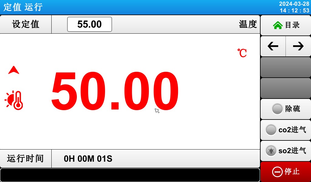
[Figure 3-5] Fixed-Value (FIX) Operation: Screen 1
① Indicates the current temperature setpoint.
② indicates the current temperature.
③ Current runtime.
④ Displays the current date and time; tap to turn off the LCD screen.
⑤ Switch from the current screen to the next screen.
⑥ Push-button switches for desulfurization, CO₂ inlet, and SO₂ inlet.
⑦ Start and Stop function keys.
3.2.3 Fixed-Value (FIX) Operation: Screen 2
▶Display screen showing command values, setpoints, control output values, and the operating status of the status indicators.


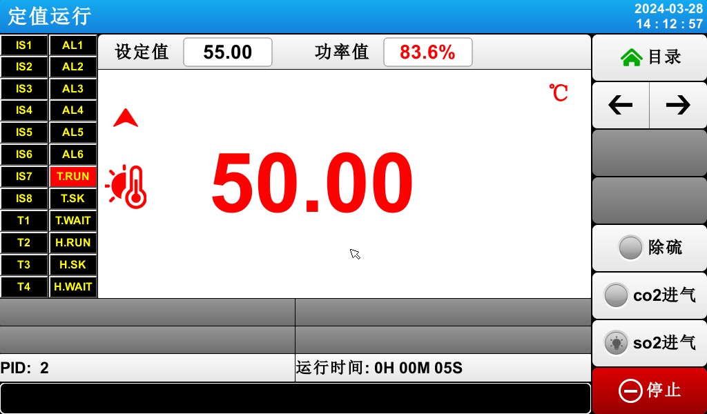

[Figure 3-6] Fixed-Value (FIX) Operation: Screen 2
The ON state is shown in red, and the OFF state is shown in dark gray.
Indicates the current temperature control output value.
Indicates the number of the currently active PID zone.
④ Indicates the duration of fixed-value operation.
3.2.4 Fixed-Value (FIX) Operation: Screen 3
▶ The left side of the screen displays the setpoint values for temperature and humidity, as well as the control output values.
▶ Use the checkbox to specify whether to display the data.


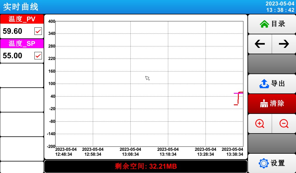
[Figure 3-7] Fixed-Value (FIX) Operation: Screen 3
① The command value, setpoint, and control output value representing the current temperature.
= 2 * GB3② Export the curve.
= 3 * GB3③ Delete the current test curve.
☞ With a sampling interval of 30 seconds, data can be stored for approximately 56 days.
3.2.5 Fixed-Value (FIX) Operation Stop Screen
▶ Once the time set in [4. Operation Settings] has elapsed, the operation ends. As shown in the figure below, a “Test Complete” message will appear, and the fixed-value operation will terminate.
▶ If you click the “Stop” button to forcefully terminate the program while it is running, no message will appear on the screen.
▶ If a message indicating that the operation has ended appears when the operation ends, tap that area of the screen, and the message will disappear.
☞ The same applies when the program terminates.
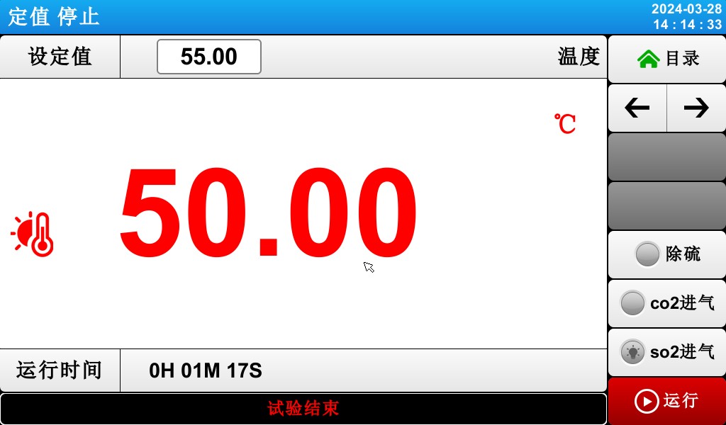
[Figure 3-8] Fixed-Value (FIX) Operation Stop Screen
3.3 Program Execution
3.3.1 Program Execution: Stop Screen 1
▶ When you select “Monitor Screen” on [3.1 Main Screen], the display switches to “Program (PROGRAM) Run: Run 1 Screen.”
▶ In [4. Operation Settings], select “Program” as the operating mode.
▶For instructions on how to configure the program, please refer to [5.1 Program Configuration].
▶ In [Figure 3-9: Program (PROGRAM) Stop Screen 1], clicking the (Run) button at the bottom right will switch to [Figure 3-10: Program (PROGRAM) Run Screen 1].
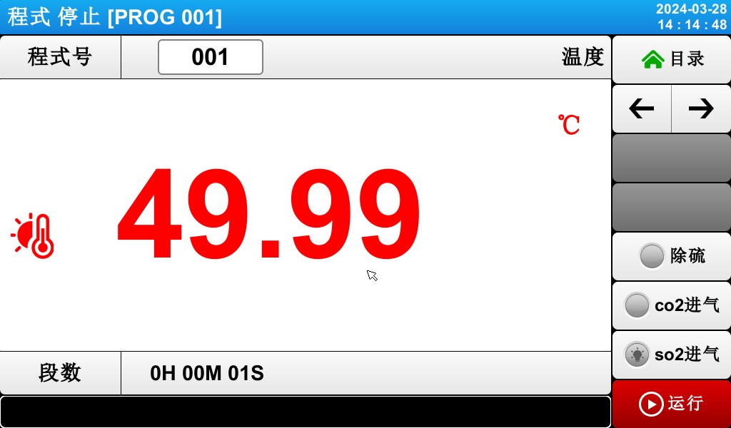
[Figure 3-9] Program (PROGRAM) Stop Screen 1
Notes on Running the Program:
▶If the number of segments is shown as 0, the program will not run.
3.3.2 Program Execution: First Execution Screen
[Figure 3-10] Program (PROGRAM) First Run Screen


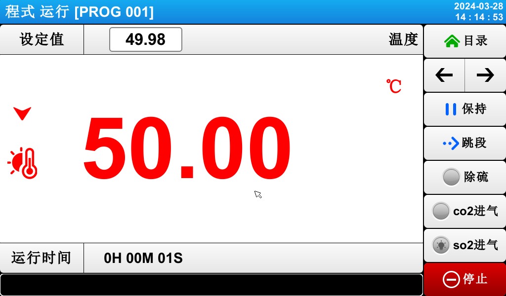
① Indicates the temperature setpoint for the currently running segment.
② indicates the current temperature.
③ Return to the menu screen.
④ Displays the current date and time; tap to turn off the LCD screen.
⑤ Return to the main page.
⑥ Switch to the next operation screen.
⑦ Pause the current operating mode.
⑧ Skip to the next segment and execute it.
⑨ Push-button switches for desulfurization, CO₂ inlet, and SO₂ inlet.
⑩ Key to stop fixed-value operation.
☞ The (Run) button is displayed on the setpoint stop screen.
※ On the program pause screen, keys ⑤ through ⑧ are disabled.
3.3.3 Program Execution: Run Screen 2
▶ Screen displaying command values, setpoints, control output values, and the operating status of status lights


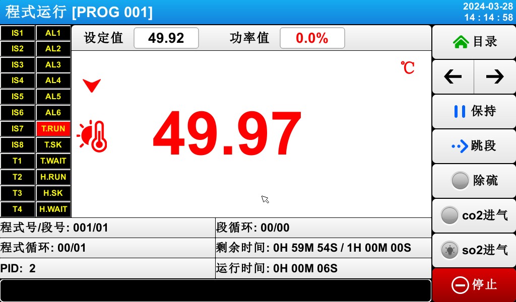
[Figure 3-11] Program (PROGRAM) Screen 2
① The ON state is shown in red, and the OFF state is shown in dark gray.
② Indicates the program number and segment number of the currently running program.
③ Indicates a program loop.
☞ [Group Cycle: 000/000] The first number indicates the number of cycles completed, and the second number indicates the set
반복 횟수.
④ Indicates the currently active PID ZONE number.
⑤ Indicates a partial loop state.
☞ [SEG Cycle Count: 00/00] The first number indicates the number of cycles already executed, and the second number indicates the set number of cycles.
⑥ Displays the elapsed time and the set time for the currently playing segment.
☞ [SEG Time: 000H00M/000H00M] The first time value indicates the duration of the segment, and the second time value indicates the time set in [5.1 Program Group Mode Settings].
⑦ Indicates the elapsed time of the program’s execution.
3.3.4 Program Execution: Screen 3


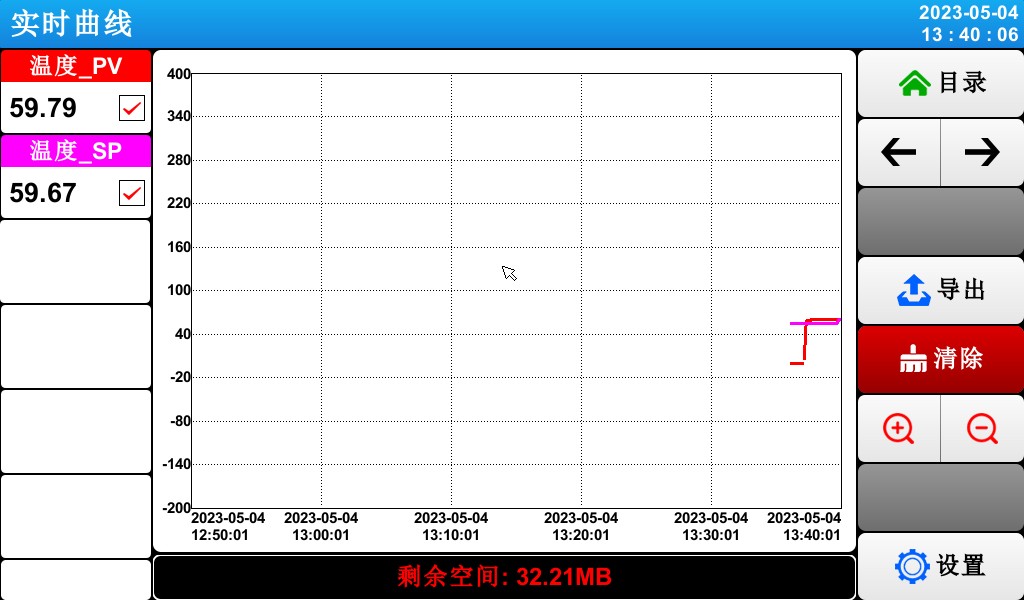
[Figure 3-7] Fixed-Value (FIX) Operation: Screen 3
① The command value, setpoint, and control output value representing the current temperature.
= 2 * GB3② Export the curve.
= 3 * GB3③ Delete the current test curve.
☞ With a sampling interval of 30 seconds, data can be stored for approximately 56 days.
3.3.5 Program (PROGRAM) Run/Stop Screen
▶ Once the program has run through all the set intervals for the segments stored in the mode, a “Test Complete” message will appear as shown in the figure, and the program will then terminate.
▶ If you click the “Stop” button to force the program to close while it is running, no message will appear on the screen.
▶ If a message indicating that the operation has ended appears when the operation ends, tap that part of the screen, and the message will disappear.
☞ The same applies when fixed-value operation ends.
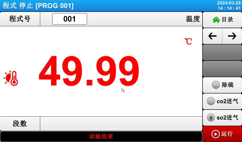
Figure 3-13: Program Stop Screen
4. Configure Related Operations
4.1 First Screen of Operation Settings


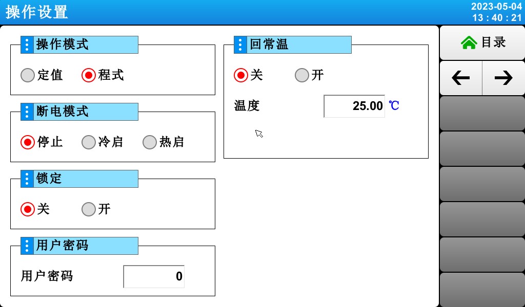
[Figure 4-1] Screen for Configuring Operation-Related Settings
① Select a setting from either “Program” (pgm) or “Fixed” (FIX) operation.
② Configure the power-on procedure in the event of a power outage.
☞ Stop: An operation that restores the system to the “Stop” state when power is restored after a power outage during operation.
☞ Cold Start: The process of restarting operations after a power outage.
☞ Hot Start: An operation that restores the system to its pre-power-loss state when power is restored after an interruption.
③ When the lock is set to “On,” none of the parameter (PARAMETER) settings can be used.
④ Go to the Lock Settings [Screen 4-3].
4.2 Second Screen for Operation Settings


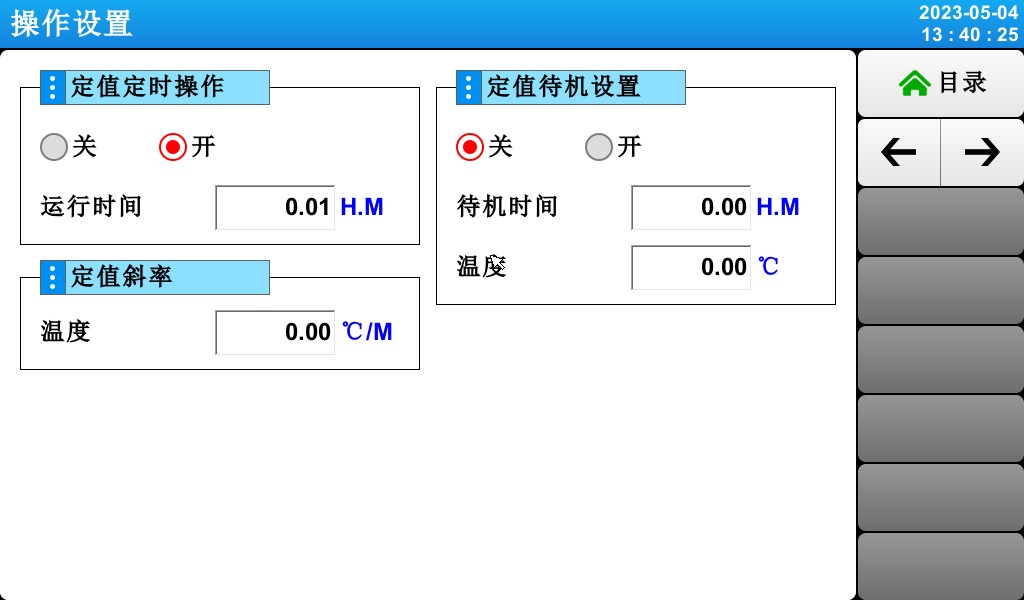
[Figure 4-2] Screen for Configuring Operation-Related Settings
① Set the fixed-value timer switch and the timer runtime.
② Set the slope for the constant temperature and humidity.
③ Fixed-value standby setting.
5. Program Group Settings
▶ Tap the program group settings button in [3.1 Main Screen] to switch to the [Figure 5-1 Program Group Settings Screen].
▶ Screen for setting parameters (PARAMETER) related to program group execution


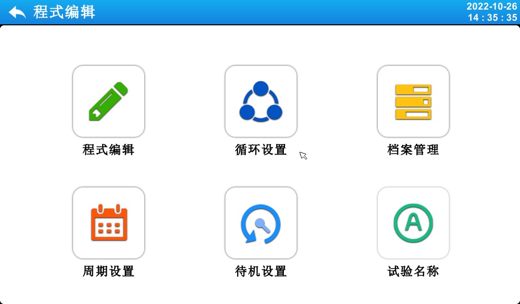
[Figure 5-1] Program Settings Screen

| 번호 | 명령 | 내용 설명 |
| ① | 프로그램 편집 | Switch to the program editing screen |
| ② | Loop Settings | Switch to the loop setting mode and the partial loop screen |
| ③ | 기록 관리 | Switch to the settings screen for copying and deleting |
| ④ | Cycle Settings | Switch to the cycle settings screen |
| ⑤ | Waiting for configuration | Switch to the screen for setting the wait action |
| ⑥ | 테스트 이름 | Switch to the screen for setting the test name |
5.1 Program Editing Settings
▶ Screen for setting segments by program number.
▶ For time signal settings, refer to [5.4 Time Signal Operation].
▶ For information on wait actions, see [5.5 Wait Actions].


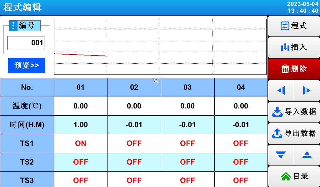
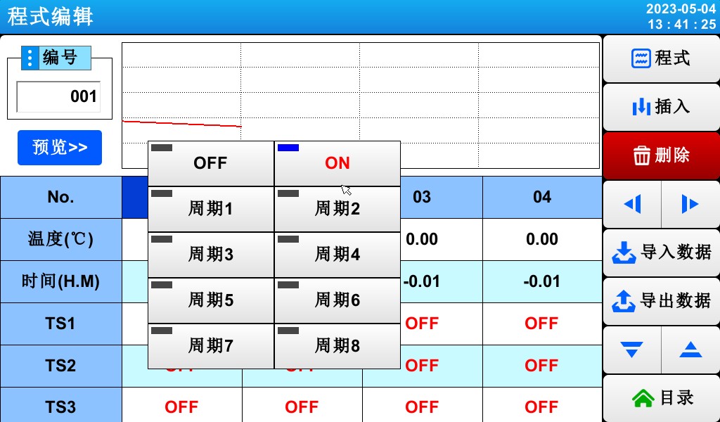
[Figure 5-2] Mode Edit Screen
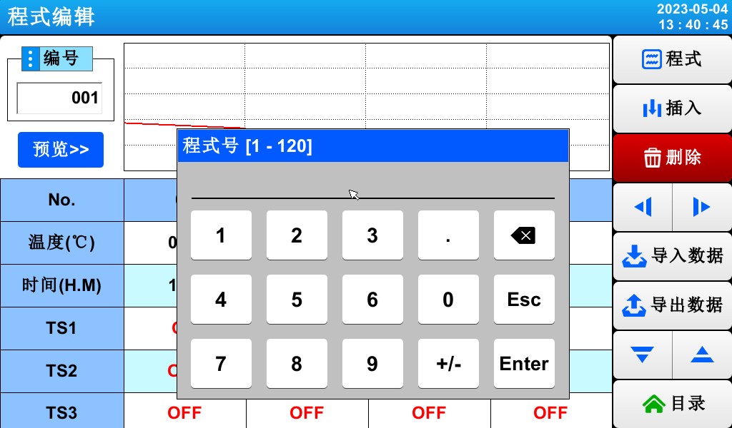
= 1 * GB3① Enter the program group number.
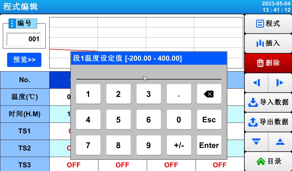
② Set the temperature for the program segment to be run.
= 3 * GB3③ Set the humidity for the program segment to be run.
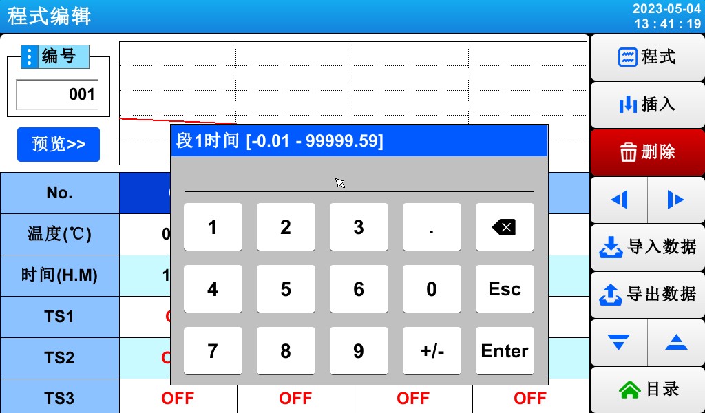
④ Set the duration for the program segment to be executed.
⑤ You can choose whether to use the wait action for the corresponding program segment.
☞ See [5.5 Waiting Actions]
⑥ Set the timing signal for the program segment to be executed
☞ Six time signals can be set for each program segment, and each time signal can be selected from among 12 types.
☞ See [5.4 Time Signal Operations]
= 7 * GB3⑦ When inserting a program segment, select a key from (Program Segments 01–99), then click to activate both the selected key in (Program Segments 01–99) and the (Insert) key. Clicking the (Insert) key inserts the program segment.
= 8 * GB3⑧ To delete a program segment, select a key from (Program Segments 01–99), then click it to activate the selected key and the (Delete) key. Click the (Delete) key to delete the program segment.
⑨ You can move the video to the left or backward in increments of 4 segments.
⑩ Switch to the second screen in the program editor.
▶ Press the (Program Number) key to display the input field for entering the program number.
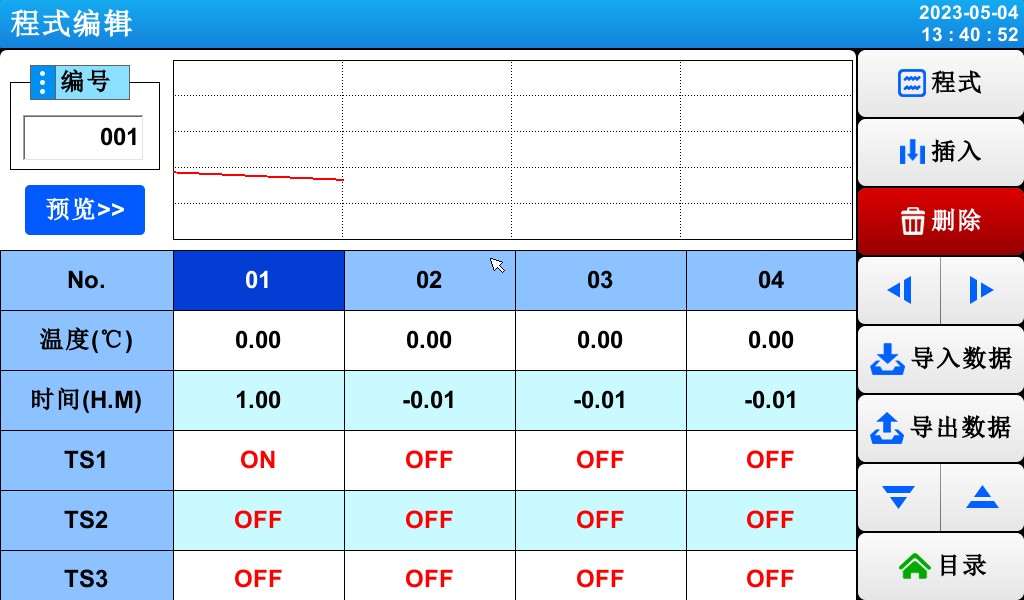
▶ Press the Activate (Section 01) key to enable the (Insert) and (Delete) keys.
▶ Press the (Temperature) button to display the input field for the set temperature.
▶ Click the (Time) button to display the input field for setting the time.
▶ Click the (TS) button to display the input field for setting the time period.
5.2 Program Loop Settings
▶ A screen for configuring the loop function—either in whole or in part—for a predefined program.


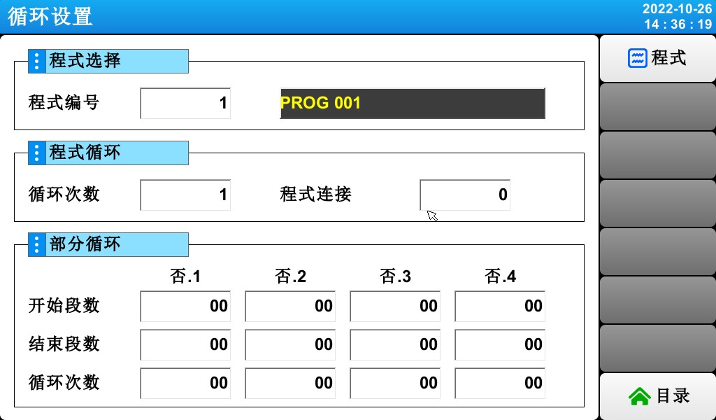
[Figure 5-3] Program and Partial Loop Settings Screen
① Set the program number for the cycle to be executed.
② Set the number of times the programmed sequence will repeat.
③ Set the program number for the program that will run continuously when the currently running program ends.
④ Set the program segment where the loop begins within the predefined program.
⑤ Set the program segment that terminates the loop in the predefined program.
⑥ Set the number of times a specific section of the program will be repeated.
⑦ Enter a name for the programmed experiment.
☞ You can change the experiment name in [5.6 Setting the Experiment Name].
☞ Read-only (READ ONLY) status; cannot be changed.
5.3 기록 관리
▶ In [5.1 Program Group Settings], you can copy parameter values entered in a program to other programs, or delete them.
▶ You cannot delete a program number that is currently running.

▶ Deleted programs cannot be restored.


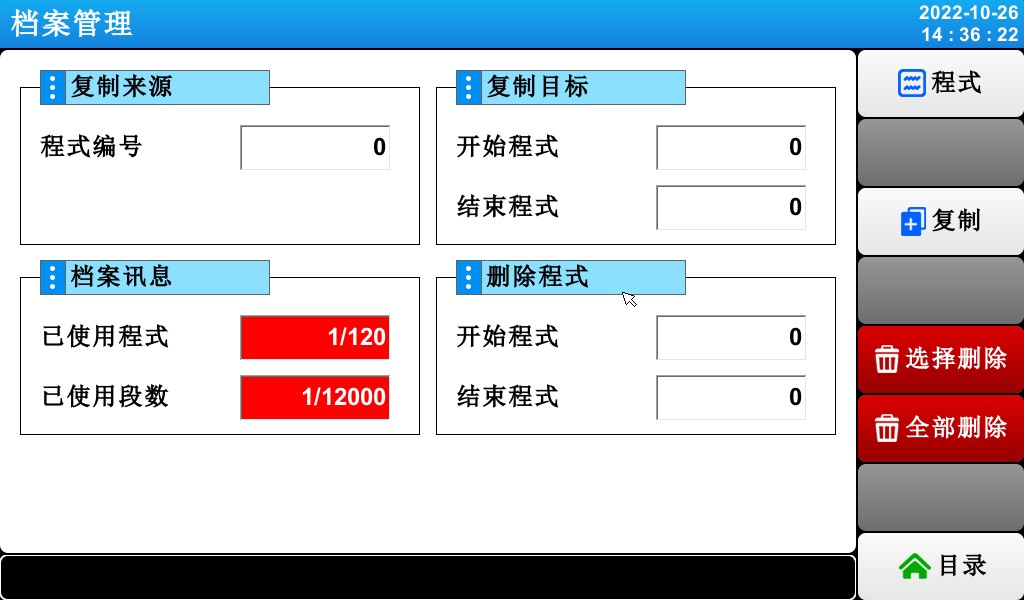
[Figure 5-4] Records Management

① Set the original program number to be copied.
② Set the starting and ending numbers for the program to be copied.
☞ When the trailing digit is “0,” only the beginning of the program is copied.
③ Displays the total number of programs configured in [5.1 Program Group Mode Settings].
☞ Read-only (READ ONLY) status; cannot be changed.
④ The total number of program segments set is displayed in [5.1 Program Group Mode Settings].
☞ Read-only (READ ONLY) status; cannot be changed.
⑤ Set the starting and ending numbers of the programs to be deleted.
☞ If the last program number is “0,” only the first program is deleted.
⑥ Copy the program set up in step ① into the program set up in step ②.
⑦ Initialize the program settings defined in ⑤.
⑧ Initialize the settings for all programs.
5.4 Cycle Settings
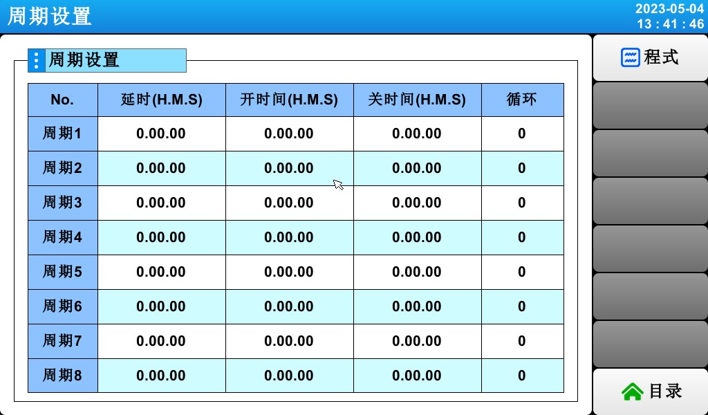
▶ Cycle settings consist of ON/OFF operations and time cycle settings. The cycle set here is used when configuring the time signal cycle in the program segment settings under [5.1 Program Group Mode Settings].
5.5 Standby Settings
▶ A screen for setting the temperature and humidity ranges and the duration of the wait while the program is running.
▶ The wait action configured here applies to [5.1 Program Group Settings].
Waiting for action definition
① Wait for the action to meet the condition (“OR” condition)
☞ If, during the set program period, either the temperature or humidity falls outside the range specified for the next action,
② Wait for the action to be triggered (an “AND” condition)
☞ When both the temperature and humidity fall within the range set for the action
③ If no wait time (initial value) is specified, the default wait time is infinite.


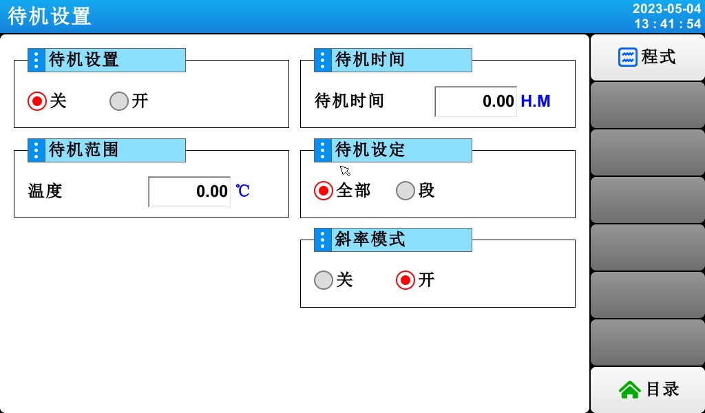
[Figure 5-10] Standby Settings
① Set whether to use the “Wait” action.
② Set the temperature range for which the wait action applies.
③ Set the humidity range for which the wait action applies.
④ The wait time to be applied when the setpoint for the temperature or humidity terminal (TEMP PV or HUMI PV) falls outside the wait action range.
☞ If the wait time is set to 00.00, the system will wait indefinitely until it enters the wait action range.
⑤ Standby Settings.
⑥ Set whether to use linear mode.
5.6 Setting the Experiment Name
▶ Set the name for each program experiment.
▶ Please refer to [Figure 3-9: Program Execution (PROGRAM) – Screen 1]


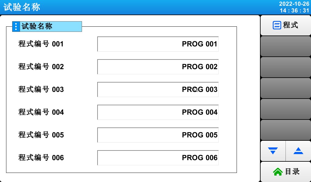
[Figure 5-11] Experiment Name Setup Screen
① Enter the experiment name for each program.
② Switch to the screen showing the previous or next experiment name.
▶ Click the (Name) button to display the input field for setting the experiment name.
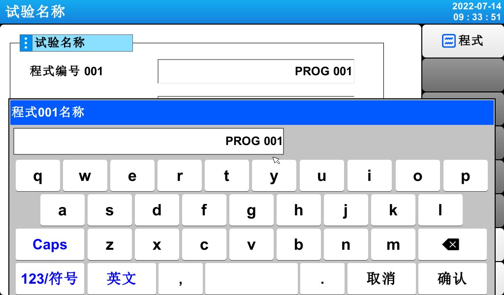
[Figure 5-12] Experiment Name Input Screen
* You can enter up to 20 characters (10 Chinese characters)
6. Historical Trends and Storage Devices
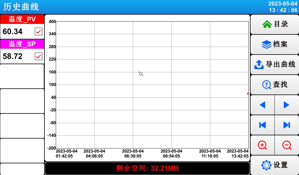
[Figure 6-1] Historical Curve Display Screen
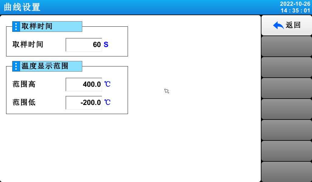
[Figure 6-2] Curve Settings Screen
7 디스플레이 설정
7.1 디스플레이 설정


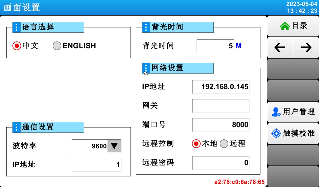
[Figure 7-1] Screen Display Settings
① Language selection.
② Set the communication address
Whether the setting button is displayed on the monitoring screen.
③ You can set the backlight power-saving timer.
☞ The “Energy-Saving Timer” setting determines how long it takes for the backlight to turn off when no buttons are pressed.
④ Set the network address and user password.
7.2 Viewing DI Failure Logs
▶ A screen displaying the type of DI fault that occurred, along with the date and time.
▶ Up to 30 fault records can be displayed.
☞ If the number of faults exceeds 30, start deleting them starting with the earliest fault number; subsequent faults will be appended to the end.
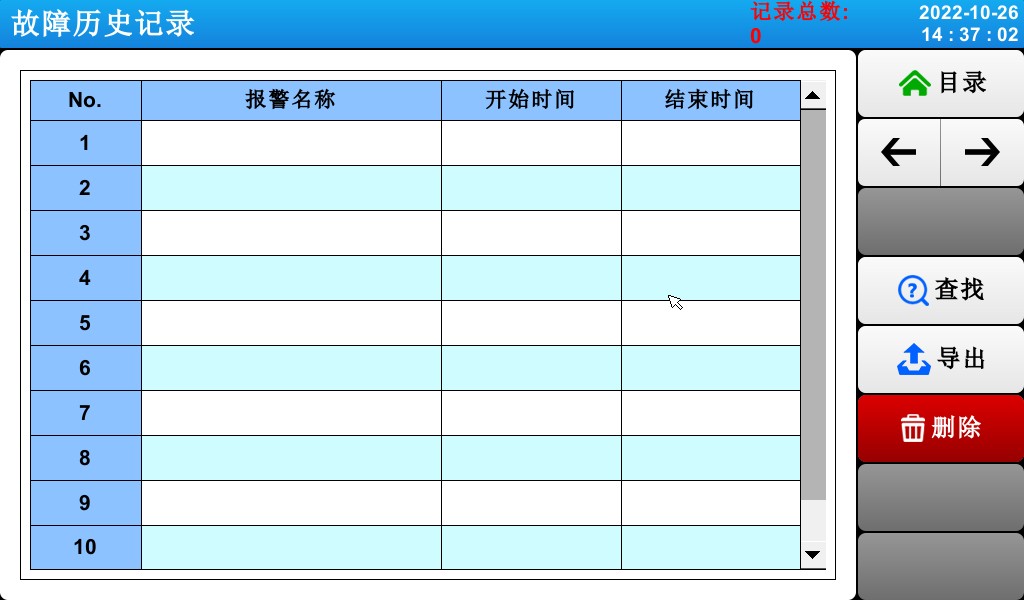
[Figure 7-2] DI Fault Log Screen
① Displays a record of DI faults.
☞ Displays the name specified in [11.2 Fault Name] of the [Installation Manual].
☞ Read-only status; cannot be changed.
② Delete all records of DI failures.
③ You can view the previous or next fault record.
8. Time Settings
▶ Screen for setting the current time and scheduled run times.


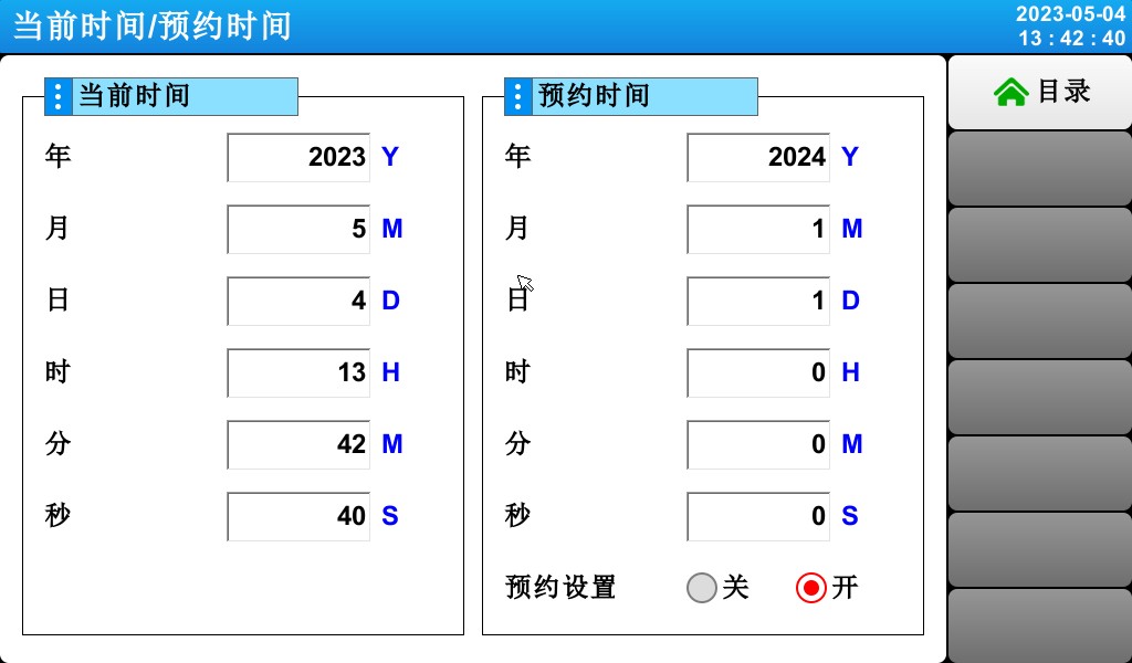
[Figure 8-1] Time Settings Screen
① Set the current year, month, day, and time.
☞ Do not change the current time while the program is running.
② Set the year, month, day, and time for the scheduled run.
③ Click the (Schedule) button to run the program at the scheduled time.
☞ Click the (Schedule) button; as shown in [Figure 8-2: Operation Schedule Settings Screen], the scheduled time will appear on the operation screen.
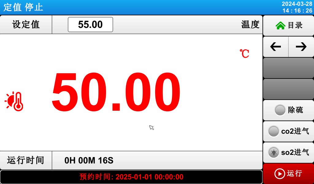
[Figure 8-2] The appointment reminder displays the monitoring screen
9 Communication Failures
▶ If the connection to the control board is abnormal, a “Control Module Not Connected” message will appear.
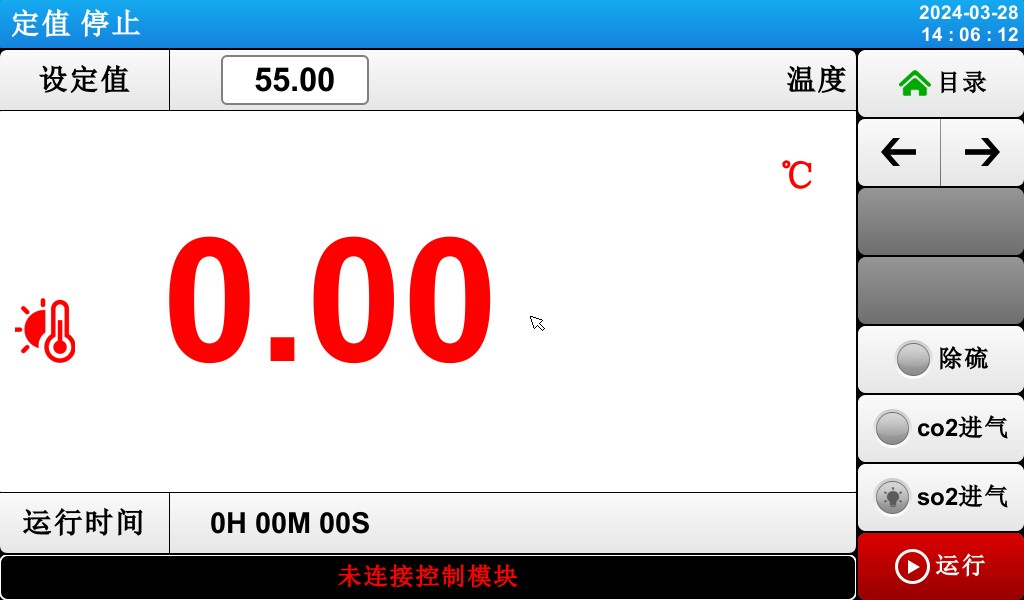
[Figure 10-1] Communication Failure Screen
Causes of Communication Outages:
Poor Communication Connection
Poor connection status of the communication link
Photometric, Colorimetric, and Safety Performance Testing Solutions for LEDs
고니오포토미터 시스템: LSG-6000, LSG-1890B및 LSG-1800ACCD
Spectroradiometer & Integrating Sphere Test System: LPCE-2 or LPCE-3
LED Life Maintains a Test System in Accordance with LM-84: LEDLM-84PL
Photobiological Radiation Safety Test System: EN 62471-C or EN 62471-P
Lamp Start, Run-up Time, and Flicker Test System: LSRF-3 LSP-500VARC-Pst
LED Power Driver Testers: LS2090, M9822예산 및 LSP-500VARC
IK Level Tester | Spring Hammer Impact Tester: IK07-10, IK01-06
전기역학적 진동 발생기 시스템: LVD-100KG-6D
Electrical Safety Testers: LS9955, ZRS-3H, ZY-3, TTC-1
LED 등기구용 환경 챔버 테스트 솔루션
Waterproof Test for IPX5 and IPX6: JL-56
Dustproof Testing Machine for IP5X and IP6X: SC-015
High and Low Temperature and Humidity Chamber: GDJS-015B
Salt Spray Test Machine: YWX/Q-010
UV Lamp Aging Test Chamber: UV-263LS
크세논 램프 노화 테스트 챔버: XD-80LS
오존 시험 챔버: OTC-150A
이산화황 시험 챔버: SQ-010
EMC and EMI Test Solutions for CFL and LED Luminaires
EMI Test System: EMI-9KB or EMI-9KA
Electrostatic Discharge Simulator: ESD61000-2
EFT Immunity Measurement: EFT61000-4
서지 생성기: SG61000-5
Voltage Dips and Interruptions Generator: CSS61000-11
Ring Wave Generator: RWG61000-12

WWW. Lisun그룹닷컴
특허 출원
모든 권리 보유 Lisun 그룹
Subject to Change Without Notice