
 영어
영어 中文简体
中文简体 Русский
 Español
 Português
 Türkçe
 العربية
 Deutsch
 Polski
 Italiano
 Français
 한국어
한국어 ไทย
ไทย Tiếng Việt
 日本語
日本語





























임펄스 테스트 생성기
사용자 설명서
적용 할 수있는 LISUN 모델: SUG255,SUG255CX、SUG255LX,SUG255MX,SUG255PX,SUG255PX-20KV、SUG255PX-25KV,SUG255PX-30KV,SUG255PX-50KV、SUG255XX、SUG335
1. 제품 개봉 및 기본 사용법 익히기
1.1 주요 기술 사양
SUG255 시리즈 :
| LISUN 모델 | SUG255LX | SUG255MX | SUG255PX | SUG255PX-20KV | SUG255PX-25KV | SUG255PX-30KV |
| 출력 전압 범위 | 0–12kV | 0–20kV | 0–25kV | 0–30kV | ||
| Generator Internal Resistance | 12옴과 500옴 | 38옴과 500옴 | 2옴과 500옴 | |||
| 출력 전압 파형 | 1.2/50μs | |||||
| 출력 전압 극성 | 긍정적 또는 부정적 | |||||
| 운영 지침 | 수동 또는 자동 | |||||
| 측정 횟수 | 1-9999 | |||||
| 간격 | 3–9999초 | |||||
SUG335 시리즈 :
| 매개변수 범주 | 특정 사양 |
| Lightning Strike Waveform Rise Time | 1.2µs ± 30% |
| Half-value time of a falling waveform | 50µs ± 20% |
| 서지 전압 범위 | 1–12.5 kV, accuracy ≤ ±3% |
| 출력 임피던스 | 42 Ω |
| 급증 간격 | 1–99 s (configurable; complies with the requirements of Clause 14 on page 43 of IEC 60335:2010+A1:2013) |
| Number of surges | 1–9999 times (configurable) |
| 서지 극성 | Positive terminal, negative terminal |
| Waveform Detection | Features a built-in high-voltage probe that can be paired with the OSP1102 Digital Oscilloscope for waveform detection |
1.2 개봉 및 내용물 확인
1.2.1 포장 해제 및 육안 검사
기기를 개봉할 때는 날카로운 도구로 케이스에 흠집이 나지 않도록 조심스럽게 다루십시오. 개봉 후에는 먼저 기기 외관을 검사하여 눈에 띄는 변형이나 찌그러짐이 없는지, 버튼이 손상되었거나 헐거워지지 않았는지 확인하십시오.
If you find that any equipment or accessories are damaged or deformed, do not turn on the power. Please contact us immediately.
1.2.2 본체 및 부속품
Main Unit Category: 1 SUG Impulse Test Generator.
Standard Accessories: ① Power cord; ② Ground wire, used to connect to the PGND protective ground terminal; ③ Coaxial cable, used to connect to an external oscilloscope for monitoring surge waveforms; ④ Discharge tube, used to check whether the equipment is outputting a surge in the event of a malfunction; ⑤ EUT test lead, used to connect the Surge Generator to the test specimen.
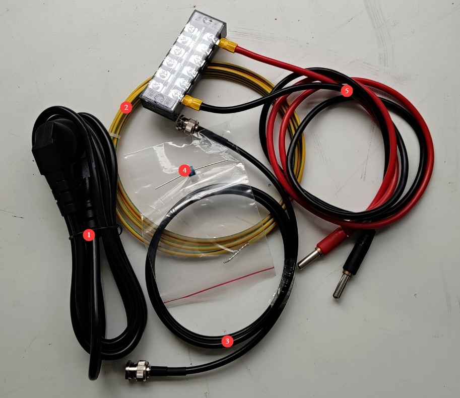
그림 1
Download links for the electronic user manual, warranty card, and other documents have been sent to you via email. Please download them as soon as possible. If you missed the email, please feel free to contact us to request the download links again.
2. 안전상의 주의
2.1 Placement Guidelines
Ensure the ambient temperature is between 15°C and 35°C, relative humidity is between 10% and 60% (no condensation), and atmospheric pressure is between 86 kPa and 106 kPa. Avoid high-voltage short circuits or damage to the equipment caused by moisture;
The premises must be free of strong electromagnetic interference, corrosive gases, flammable and explosive materials, and dust, and must be well-ventilated to prevent sparks from causing hazards;
Place it on a stable workbench; avoid tilting or inverting it, and keep it away from sources of vibration;
The equipment must be placed at least 1000 mm away from walls and surrounding structures (such as other testing equipment and shelving) to facilitate maintenance; at least 2000 mm of space must be left in front of the equipment to ensure smooth operation and that there are no obstructions in the surrounding area.
2.2 High-Voltage Safety Standards
2.2.1 보안 검색
Verify that the equipment’s power supply voltage matches the mains voltage (AC 220 V ±10%, 50/60 Hz), and confirm that the power supply is properly grounded and that the grounding wire is free of damage or looseness;
Grounding Requirements: The main unit’s protective grounding terminal (PGND) must be connected to the ground, with a grounding resistance of ≤4 Ω, to ensure safe discharge of high voltage;
Operators must have dry hands and must not wear any metal jewelry.
2.2.2 운영 절차에 대한 안전 요구 사항
Operators must undergo professional training and be familiar with this manual and the relevant standards. Non-professionals are prohibited from operating or disassembling the equipment. The equipment contains high-voltage circuits; opening the cover may pose an electric shock hazard. Contact the manufacturer’s technical staff for repairs.
The equipment generates high-voltage, high-current surges during operation. Do not touch the pulse output connector or the EUT test specimen connections under any circumstances.
During testing, unauthorized personnel are prohibited from remaining within 1 meter of the EUT to prevent accidental electric shock or interference from electrical discharges.
Before switching connections or replacing the EUT, you must first ensure that the high-voltage output is turned off (the HV indicator light is off) and wait at least 5 minutes to ensure that the internal high-voltage capacitors are completely discharged.
Do not eat or drink during the test to prevent accidents caused by electric shocks.
When multiple people are involved, roles must be clearly defined, and everyone must confirm their tasks with each other before testing begins to avoid errors.
2.3 Emergency Response Measures
In the event of an electric shock: Immediately shut off the main power to the equipment, move the operator to a safe area, administer first aid if necessary, and contact medical personnel.
Equipment Malfunction (Smoke, Unusual Noises, Unusual Odors): Immediately turn off the equipment and disconnect the power supply; disconnect all cables; do not turn the equipment back on; contact the manufacturer for repairs.
Abnormal surge output: Pause the test, contact the manufacturer for troubleshooting, and do not touch the test port directly with your hands.
2.4 기타
본 설명서에 나와 있지 않은 사항에 대해서는 주의를 기울여 진행하시거나 당사에 문의해 주십시오.
3. Operating Procedures for Pulse Withstand Voltage Testing
3.1 장비 배선
3.1.1 Introduction to the Back Panel and Wiring
① Power cord; ② Remote control (reserve port; if not specified at the time of purchase, this feature is not available); ③ Ground wire. Please refer to Section 2.2.1 for connection instructions.
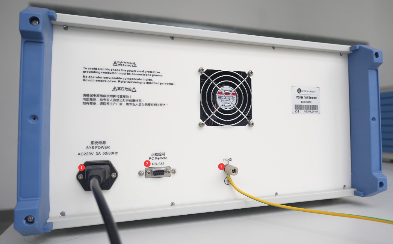
그림 2
3.1.2 Front Panel Overview and Wiring
① Power switch; ② Touchscreen; ③ EUT connection cable, with one end connected to the required impedance and the other end connected to the EUT’s high-voltage test terminal; ④ EUT connection cable, with one end connected to the COM port and the other end connected to the EUT’s ground terminal or low-potential terminal;⑤ Place the EUT on the left side of the withstand voltage tester; do not route the EUT connection cable in front of the touchscreen to avoid interfering with the touchscreen during testing; ⑥ CRO-V oscilloscope interface, which can be used to connect an external oscilloscope to monitor waveforms; ⑦ USB port, which can be used to connect a mouse or to update the software.
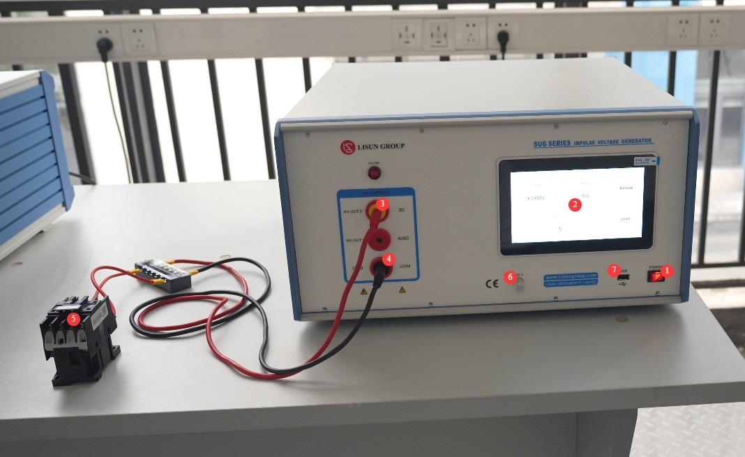
그림 3
3.2 Introduction to the Touchscreen Program and Parameter Settings
① General Precautions for Use (Functionality is not yet fully developed; do not perform any operations at this time); ② System Information Screen; ③ Switch Between Chinese and English; ④ Pulse Withstand Voltage Test Screen.
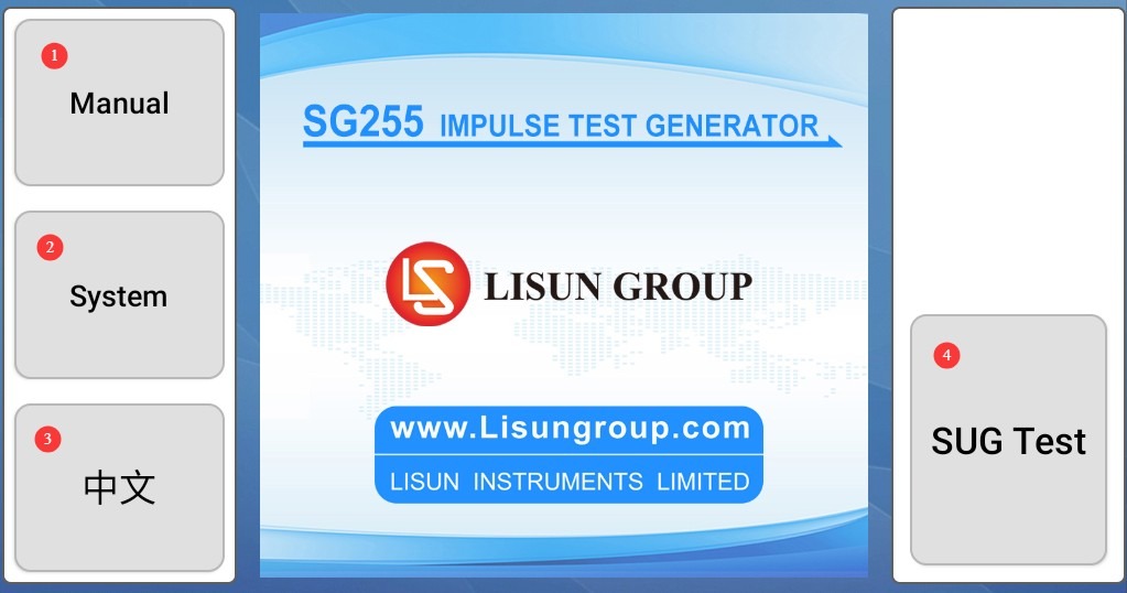
그림 4
① Test voltage and polarity settings; ② Interval time settings; ③ Number of test cycles; ④ Back; ⑤ Start/Stop test.
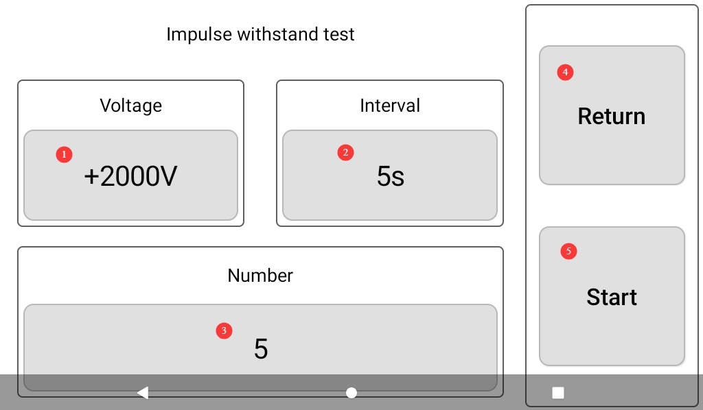
그림 5
3.3 Start Testing
After confirming that the wiring and parameter settings are correct, click “Start” to begin the test; the HV (High Voltage) indicator light will turn on.
① Set the voltage and display the current voltage; ② Countdown timer for the interval; ③ Total number of tests and current test number; ④ Tap to manually stop the current test.
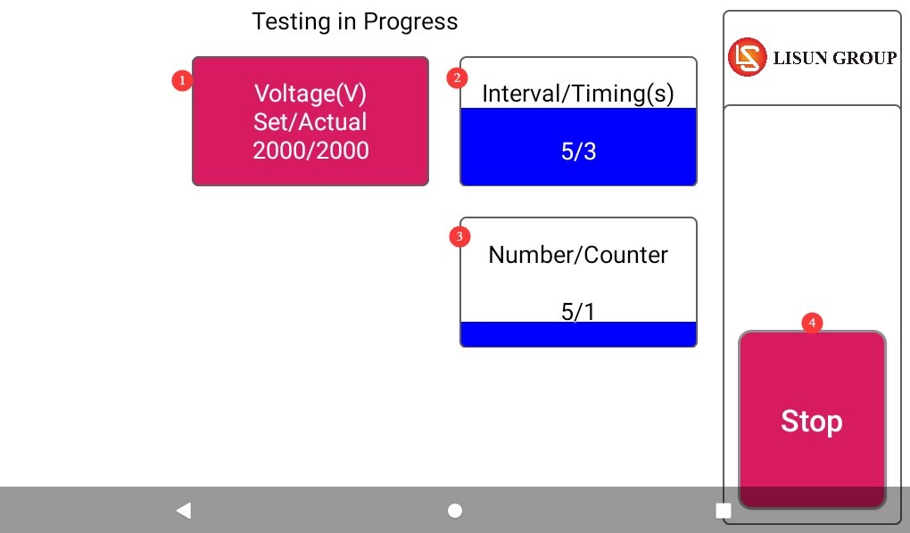
그림 6
4. 테스트 후 절차
4.1 Test Stopped
If the EUT is visibly damaged during the test, immediately tap “Stop Test” on the touchscreen.
If no errors occur during the test, wait for the test to end automatically.
Wait 5 minutes to ensure that the high-voltage capacitors inside the main unit have fully discharged, then replace the EUT for testing, or turn off the main unit’s power.
4.2 Post-Test Organization and Cleanup
Verify whether the EUT has passed the test (no performance degradation, no damage).
Clean the test area and wipe it down with a dry cloth. Do not use alcohol or corrosive cleaning agents.
The pulse withstand voltage test is a destructive test; it does not automatically generate a test report, but the device automatically saves the test data. You can go to the “System Information” screen, click “Test Log,” and export the corresponding test data to a USB flash drive via the USB port. The exported file is in TXT text format.
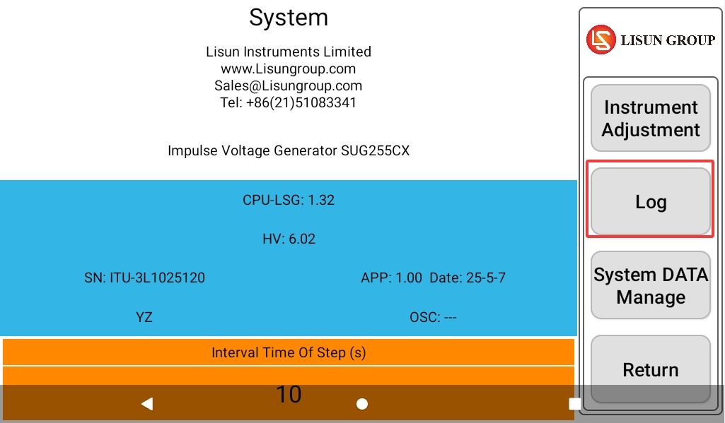
그림 7
4.3 장비 보관
4.3.1 Short-Term Storage Requirements
장비를 매일 사용하는 경우, 각 테스트 후 청소가 완료되면 추가 조치는 필요하지 않습니다.
4.3.2 장기 보관 요건
If the device will not be used for an extended period (more than 1 month), please disconnect all cables and cover the device with a dust cover to prevent dust buildup.
The device should be powered on once a month for just half an hour to prevent electrical components (such as capacitors and contactors) from deteriorating.
5. Use an external device to verify the surge output
5.1 Using an External Oscilloscope (Using the LISUN OSP Series Oscilloscope as an Example)
5.1.1 Using the CRO Port
Set the following parameters on the Impulse Test Generator: Set the voltage to +1 kV; set the interval as short as possible, such as 5 seconds; and set the number of surges to a higher value to make it easier to view each waveform.
Do not connect any EUT; ensure that the circuit is completely open. Then, use the coaxial cable provided to connect the “CRO-V” port of the Impulse Test Generator to the oscilloscope.
Press the ① “Menu” button below ② “Trigger.”
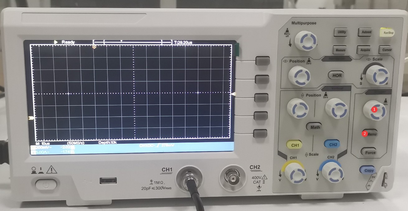
그림 25
① Select the connected channel, ② set the trigger mode to “Normal,” ③ click to proceed to the next page.
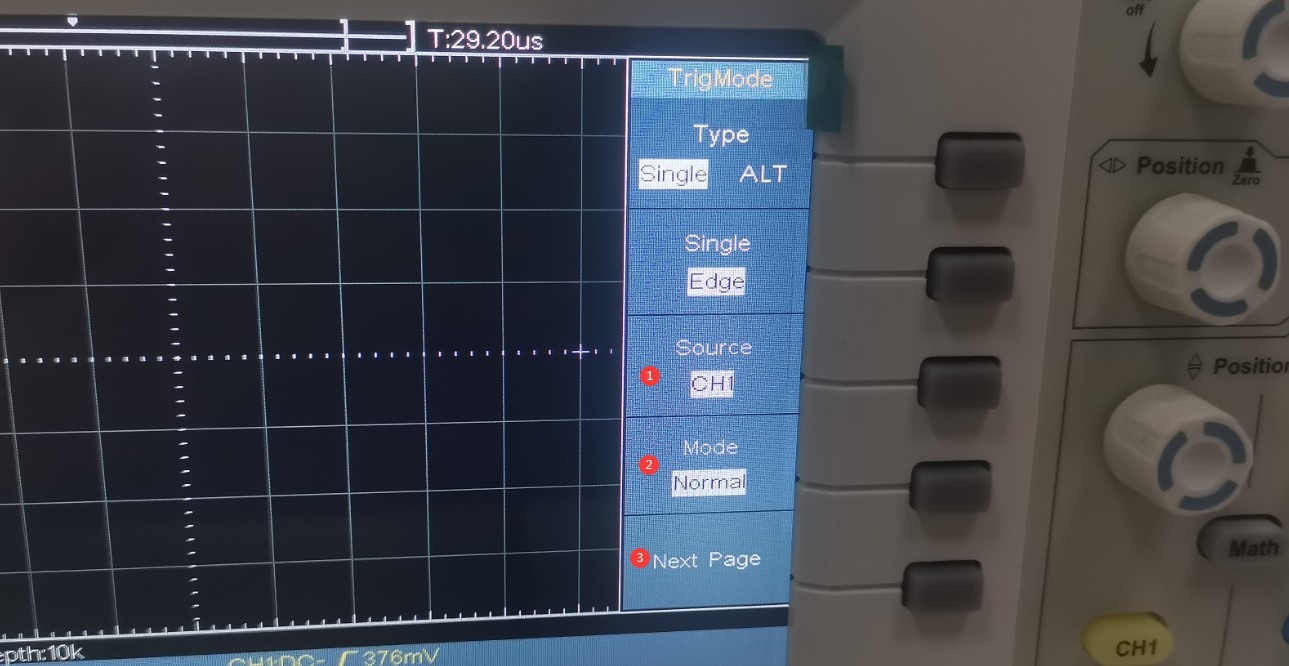
그림 26
① Select the rising edge.
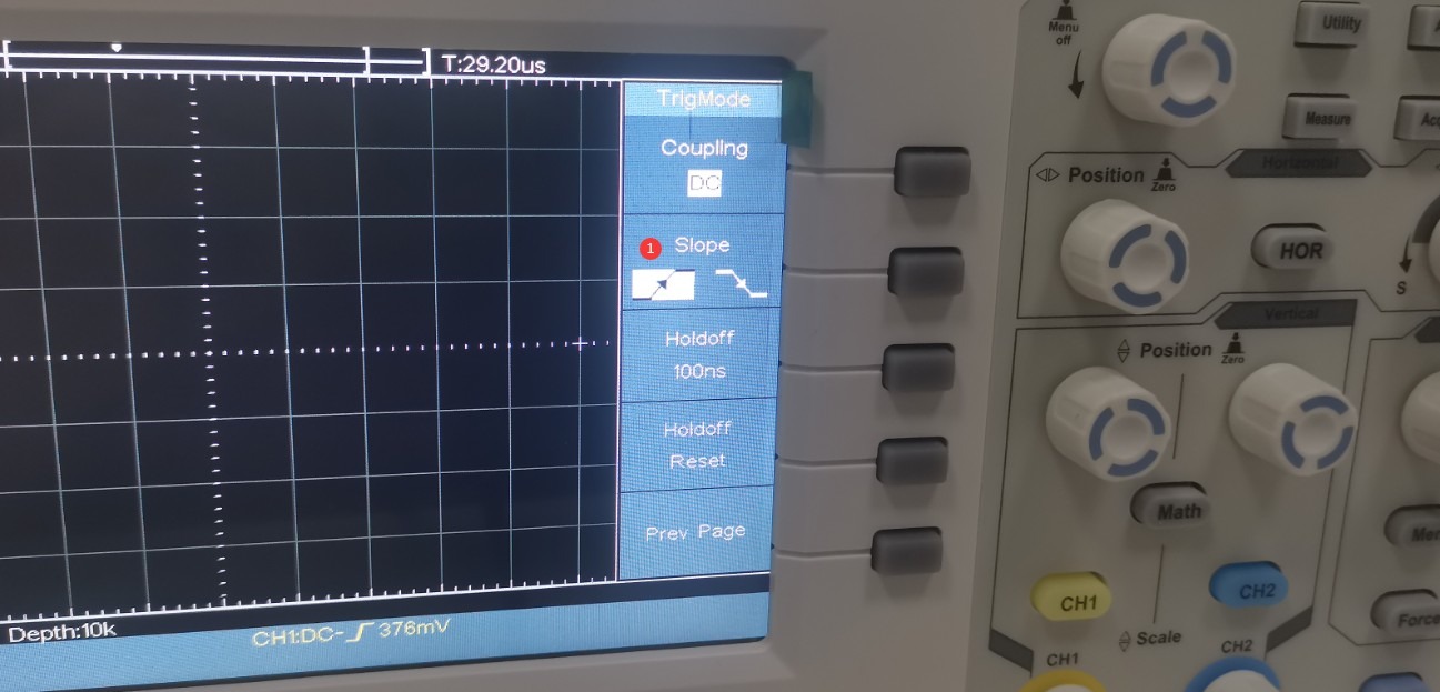
그림 27
Press the CH1 knob (①).
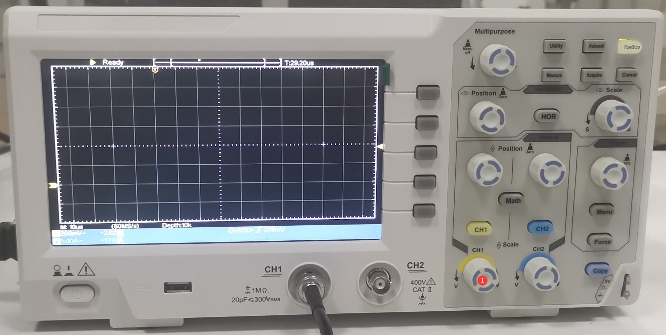
그림 28
① Select a multiplier of 1X; ② Turn off the current test function.
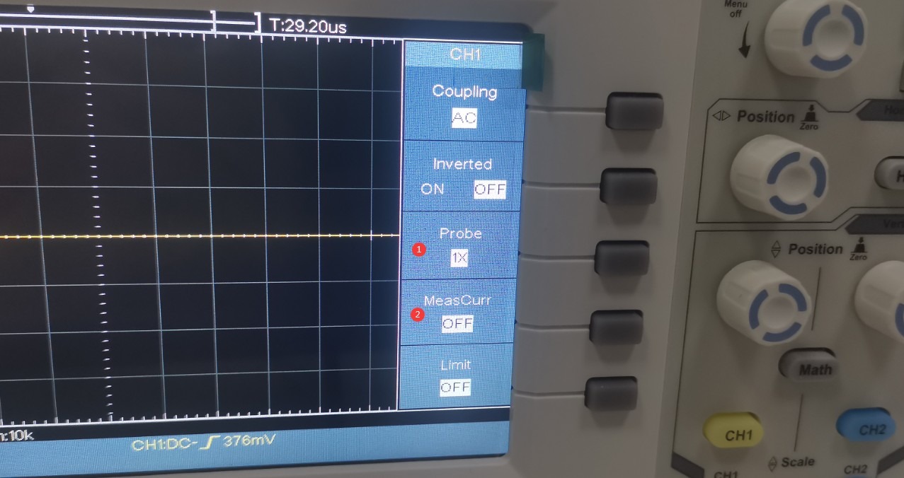
그림 29
The Impulse Test Generator has a built-in 1000:1 high-voltage Voltage Probe at the CRO interface. If the surge voltage is set to +1 kV, the actual voltage reaching the oscilloscope is 1 V. Turn the ① CH1 knob to set the ② vertical axis of the oscilloscope to 1/5 per division, or 200 mV, which makes it easier to view the entire waveform. Turn the ③ “Scale” knob to set the ④ horizontal time axis of the oscilloscope to 10 μs per division.
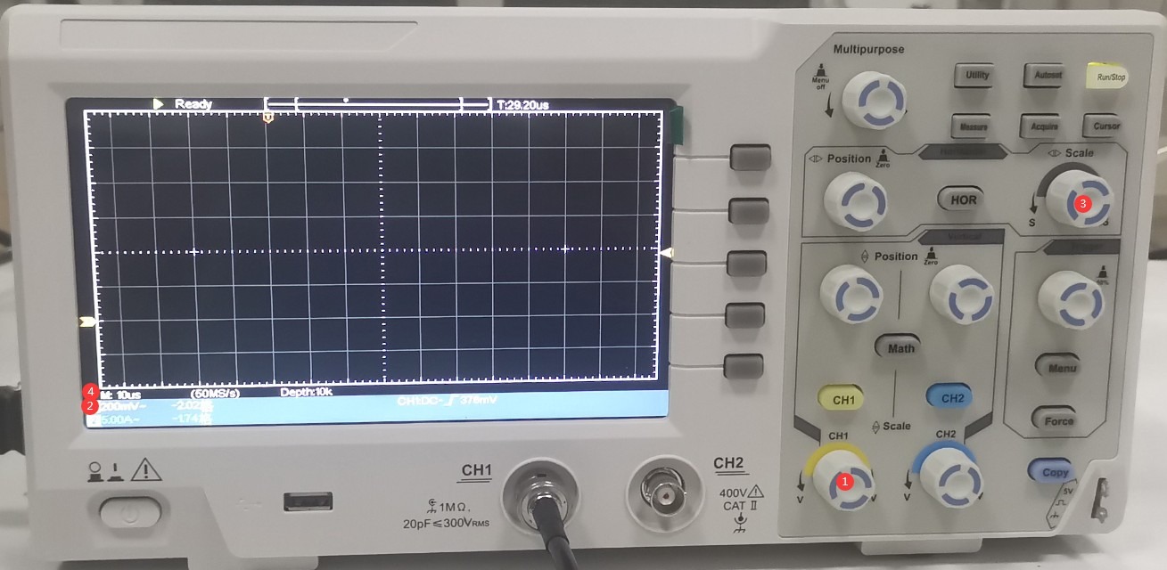
그림 30
Turn the two knobs—① (left/right) and ② (up/down)—to adjust the position of the waveform display to the appropriate location shown in the figure. Turn the ③ “Trigger” knob to adjust the level to approximately the middle position.
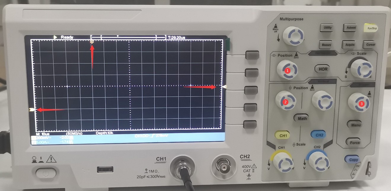
그림 31
On the touchscreen of the Impulse Test Generator, tap “Start” to begin the test. Each time a pulse is output, the oscilloscope will display a surge voltage waveform as shown in the figure below. Use the horizontal cursor to verify the output voltage; since it is set to 1 kV, the oscilloscope should display 1 V.
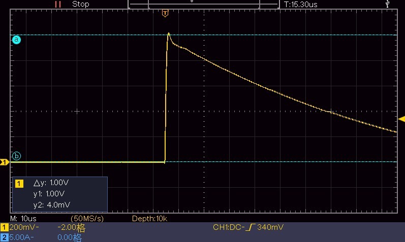
그림 32
Use the vertical cursor to confirm the surge half-width time.
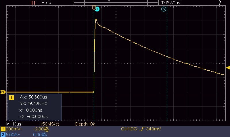
그림 33
Set the time scale to 1 μs, leaving all other settings unchanged. Wait for the next surge output, then use the vertical cursor to determine the rise time of the surge.
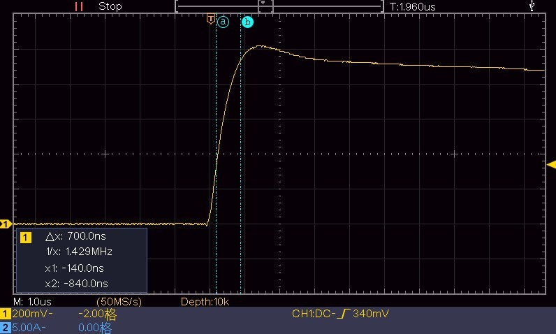
그림 34
5.1.2 Connecting to the EUT Port
Connecting an external oscilloscope to the CRO port is intended solely for the user’s convenience when viewing waveforms. However, if the device needs to be calibrated, you must provide your own high-voltage probe and connect the oscilloscope directly to the EUT connection port on the front panel of the impulse withstand voltage tester. Refer to Section 5.1.1 and the scaling factor of the high-voltage probe being used when operating the oscilloscope.
5.2 Using a Discharge Tube
A discharge tube can be used to easily verify whether a device produces a surge.
Connect the discharge tube to the pulse withstand voltage tester as the EUT. Set the output voltage to 12 kV, then click “Start” to begin the surge test. The discharge tube will flash the moment the pulse is output; please dim the lights in the room to facilitate observation. See the figure below:
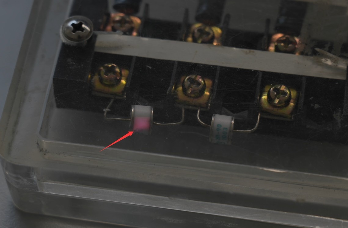
그림 35
This confirms that the device is indeed producing an output surge. If the discharge tube does not flash, please contact customer service.
6. 문제 해결 및 일반적인 문제 해결 방법
6.1 The device won’t turn on
Symptom: After turning on the power switch, the device does not respond (the indicator light does not come on, and the fan does not spin).
Possible causes: ① The power cord is not properly connected or is damaged; ② Abnormal supply voltage; ③ A blown fuse; ④ A burned-out varistor (MOV).
Troubleshooting: Ensure the power cord is intact and securely connected. Power supply issues—such as unstable voltage, excessively high voltage, or harmonic interference—can cause the fuse or varistor to burn out. It is recommended to use a voltage-stabilized, clean sine-wave AC power supply to power the device. Replace the fuse or varistor with one of the same type.
The figure below shows the location of the fuse:
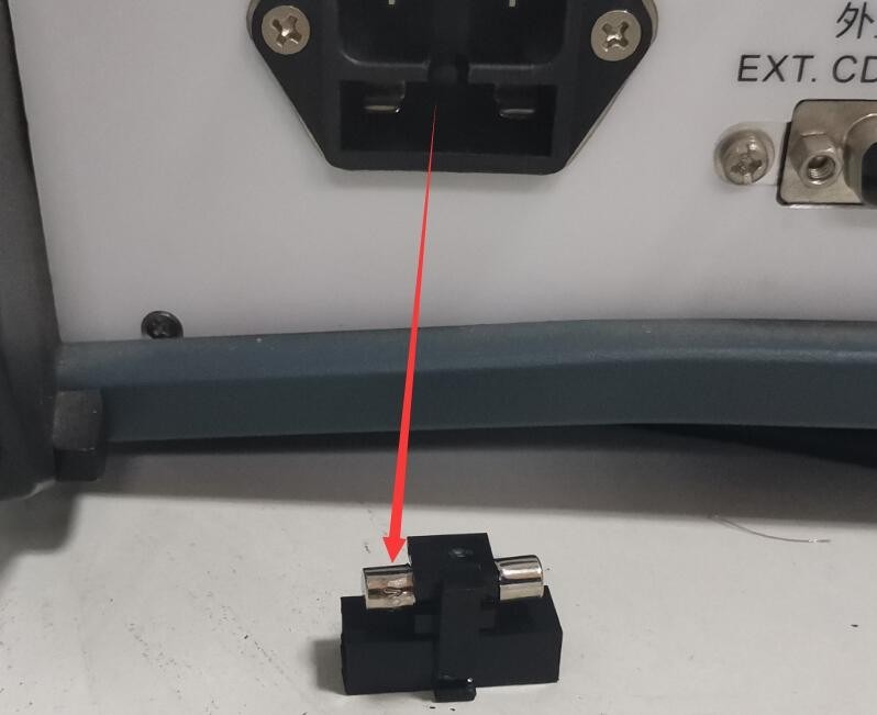
그림 39
The figure below shows the location of the varistor (MOV) inside the filtered power supply:
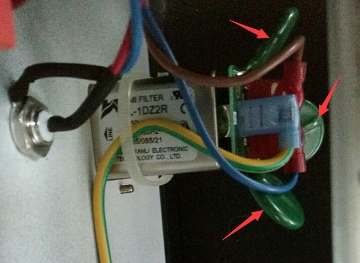
그림 40
6.2 Automatic Device Restart
Symptom: The device automatically restarts during pulse output.
Possible cause: The ground wire is not properly connected.
Solution: Refer to Section 2.2.1. Connect the PGND grounding terminal on the back of the host to ground, and ensure that the grounding resistance is ≤4Ω; otherwise, high voltage may not be safely dissipated, causing the device to automatically restart.
6.3 The waveform contains interference
Symptom: When using an external oscilloscope connected to the CRO port to inspect a standard surge waveform, some noise appears when the waveform is magnified. See the figure below:
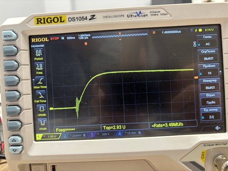
그림 41
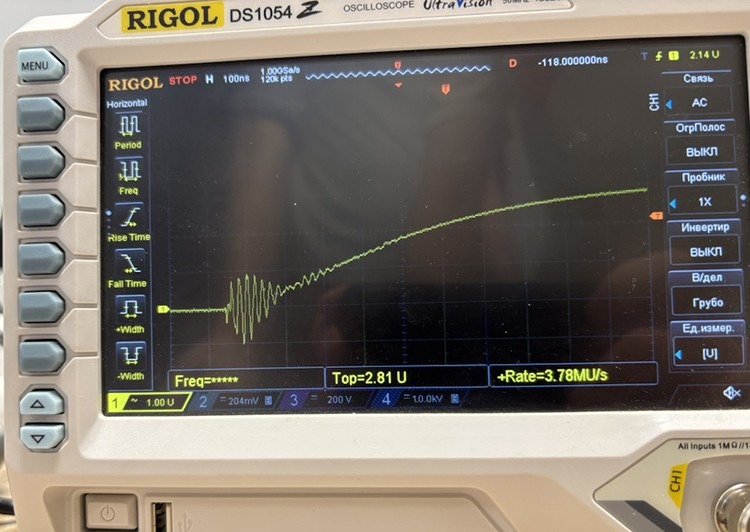
그림 42
Possible cause: The built-in digital oscilloscope and CRO port are designed to make it convenient for users to quickly and easily obtain waveform data, but they may generate a small amount of noise.
Procedure: If you need to obtain the actual output waveform of the surge generator, or if you wish to calibrate the equipment, use an oscilloscope and a high-voltage probe to directly inspect the waveform at the EUT connection port, as shown in the figure below:
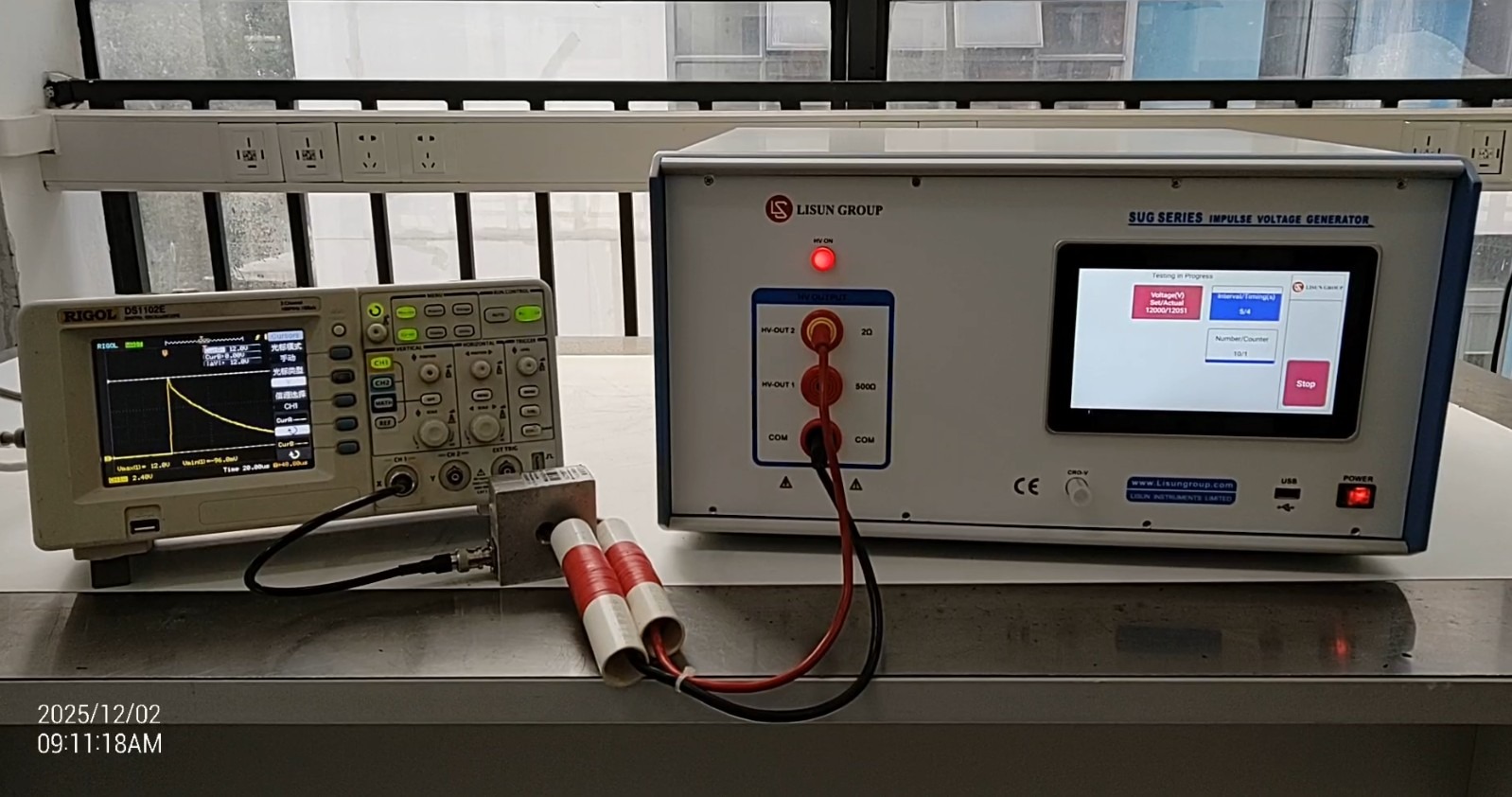
그림 43