
 영어
영어 中文简体
中文简体 Русский
 Español
 Português
 Türkçe
 العربية
 Deutsch
 Polski
 Italiano
 Français
 한국어
한국어 ไทย
ไทย Tiếng Việt
 日本語
日本語





























온도 상승 테스터
사용자 설명서
적용 할 수있는 LISUN 모델: WS-1、WS-2、WS-3
1. 제품 개봉 및 기본 사용법 익히기
1.1 주요 기술 사양
| LISUN 모델 | WS-1 | WS-2 | WS-3 |
| 테스트 스테이션 | 8 | ||
| 테스트 전류 | 0–50A | 0–200A | 0–300A |
| 시험 전압 | 3V 미만 | ||
| 타이머 기능 | 0초에서 9999초까지 조정 가능 | ||
| 온도계 | 0–1000°C (includes 8 Type K thermocouples) | ||
| 표준에 따라 | GB/T 2099.1, 제19조 (IEC 60884-1(조항 19) | GB/T 2099.1, 제19조 (IEC 60884-1GB 16915.1 제17조(IEC 60669-1 제17조) 및 GB/T 13140.1 제15조(IEC 60998-1 제15조)의 요구사항을 준수합니다. | |
1.2 개봉 및 내용물 확인
1.2.1 포장 해제 및 육안 검사
When unpacking the device, handle it gently to avoid scratching the outer casing with sharp tools. After unpacking, first inspect the exterior of the device to ensure there is no visible deformation or dents, and that the buttons are not damaged or loose.
If you notice any damage or deformation to the equipment or accessories, do not turn on the power. Please contact us immediately.
1.2.2 본체 및 부속품
온도 상승 측정기: 1대.
The standard accessories are as follows: ① Power cord; ② Mock-up, used for testing flush-mounted electrical fixtures such as outlets; ③ Conduit; ④ 8 K-type thermocouples.
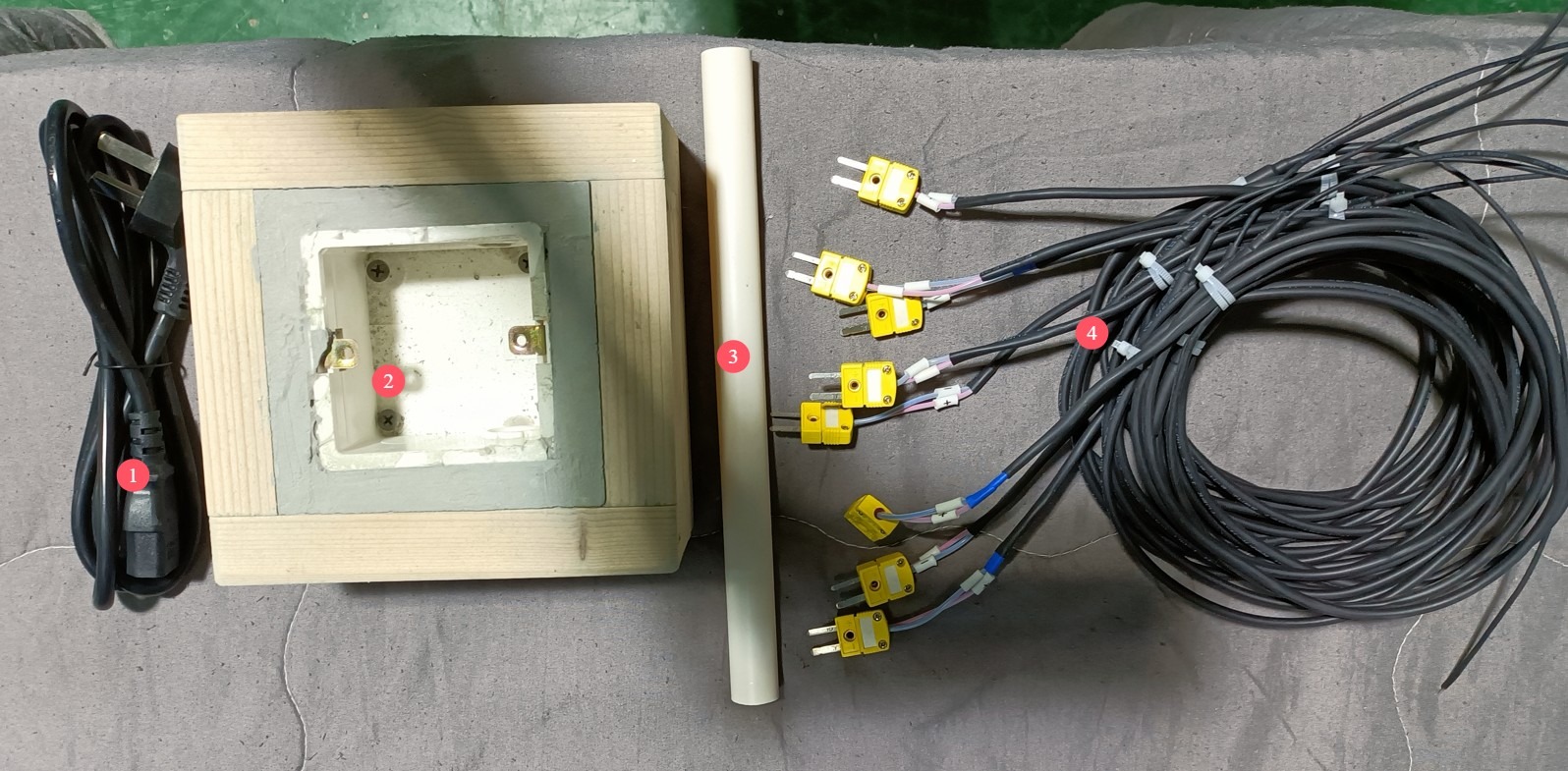
그림 1
Download links for the digital user manual, warranty card, and other documents have been sent to you via email. Please download them as soon as possible. If you missed the email, you can contact us to request the download links again.
1.3 장비 구조 설명
1.3.1 기기 전면
① Touchscreen; ② 8-channel temperature display; ③ Test current display; ④ Power switch; ⑤ Test current adjustment.
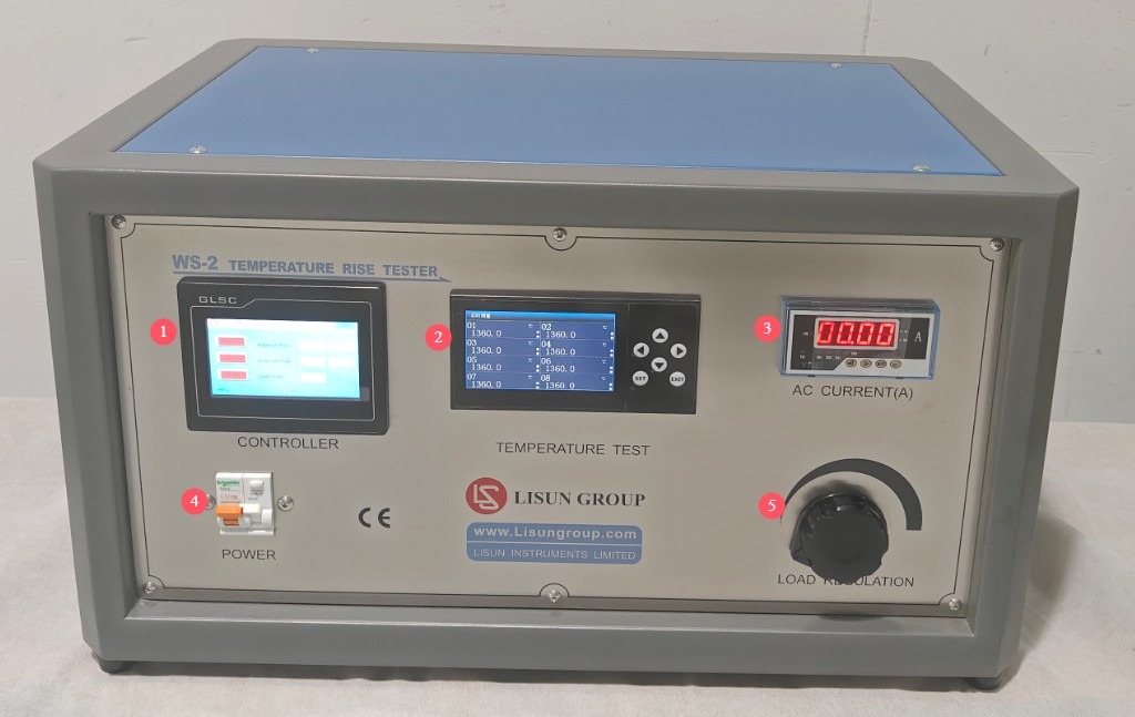
그림 2
1.3.2 Side and Back of the Device
① 8 Omega Type K thermocouple sockets; ② Sample terminals, capable of connecting 8 samples in series simultaneously; ③ Power cord jack.
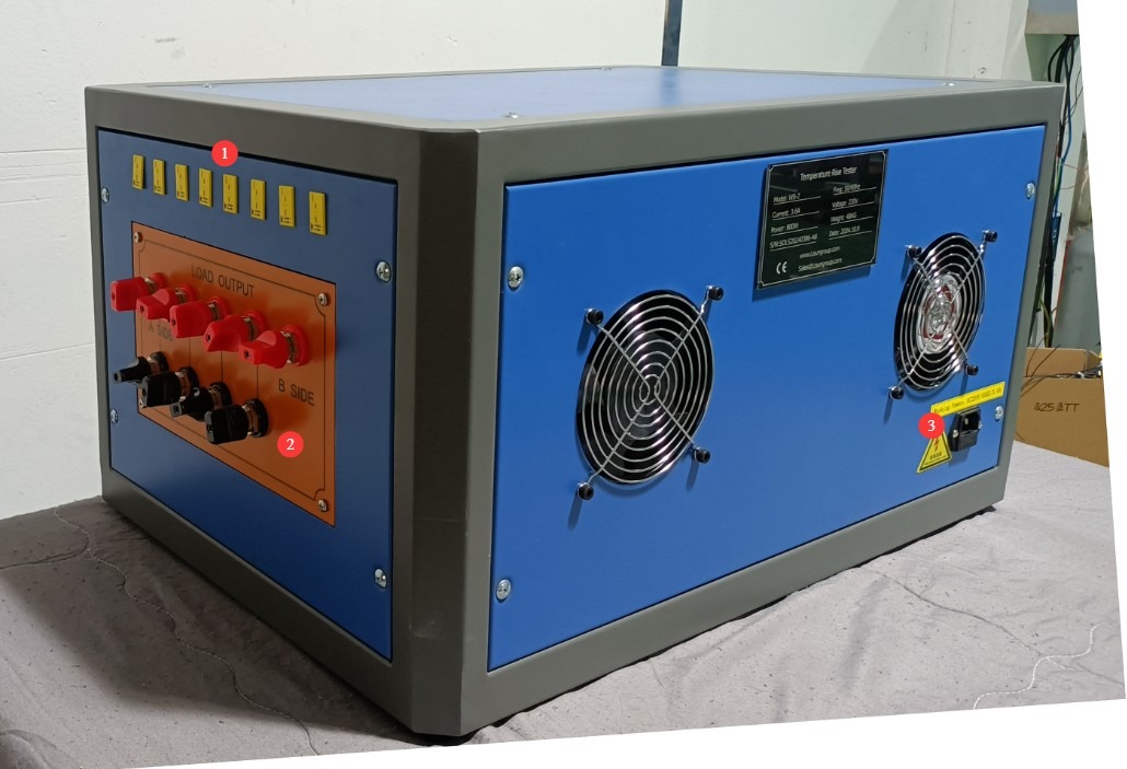
그림 3
2. 안전상의 주의
2.1 전기 안전
2.1.1 전원 연결
220V single-phase power; power outlets must comply with safety standards, have proper grounding, and have a rated current that matches the equipment’s power rating and the actual load power requirements.
2.1.2 접지 사양
The equipment must be reliably grounded, with a grounding resistance of ≤4 Ω. Do not use gas pipes, non-metallic water pipes, or neutral wires as substitutes for the grounding wire. After grounding is complete, use a Grounding Resistance Tester to measure the grounding resistance. Power may only be applied after confirming that it meets the requirements, to prevent electric shock, equipment malfunctions, or measurement errors caused by poor grounding.
2.2 작동 안전
장비 배선, 점검 또는 유지보수를 시작하기 전에 장비의 전원 스위치와 주 전원 공급 장치를 끄고 잔류 전압이 없는지 확인한 후 작업을 진행해야 합니다.
감전 위험을 방지하기 위해 젖은 손으로 장비의 전원 스위치, 터치스크린 또는 계기판 버튼을 조작하지 마십시오.
전기 제어 캐비닛 내부에는 먼지나 이물질이 들어가 단락을 일으키거나 부품을 손상시킬 수 있으므로 공구나 종이 등의 이물질을 넣지 마십시오.
장비가 작동 중일 때는 전원 코드나 신호 케이블을 연결하거나 분리하지 마십시오. 단락으로 인해 컨트롤러 또는 전기 부품이 손상될 수 있습니다.
이 장비는 높은 전류를 출력할 수 있습니다. 전선을 연결하거나, 샘플을 교체하거나, 회로를 조정할 때는 먼저 전원을 끄고 부하 전류 제어 노브를 가장 낮은 설정으로 조정하여 부하 출력이 없도록 하고 감전을 방지해야 합니다.
고온으로 인한 화상이나 감전을 방지하기 위해 시험 중에는 시료, 열전대 단자 또는 부하 출력 커넥터를 만지지 마십시오.
Warning signs must be posted in the test area to prohibit unauthorized personnel from approaching, in order to prevent accidental contact with high-temperature samples or live electrical components.
2.3 환경 안전
해당 장비는 평평하고 건조하며 환기가 잘 되는 실내 환경에 설치해야 하며, 인화성 및 폭발성 물질, 부식성 가스, 강한 자기장으로부터 멀리 떨어뜨려야 합니다.
The equipment must be installed in an air-conditioned room, with the ambient temperature maintained between 5°C and 35°C and relative humidity ≤ 85%.
The distance between the equipment and walls, as well as surrounding structures (such as other test equipment and shelving), must be at least 1000 mm to facilitate operation and maintenance; at least 2000 mm of space must be left in front of the equipment to ensure smooth operation and keep the surrounding area free of obstructions;
2.4 기타
본 설명서에 나와 있지 않은 사항에 대해서는 주의를 기울여 진행하시거나 당사에 문의해 주십시오.
3. 터치스크린 프로그램 소개
3.1 테스트 인터페이스
① Start timer; ② Start test power supply; ③ Reset; ④ Display of sample power-on duration; ⑤ Display of sample power-off duration; ⑥ Display of number of repetitions.
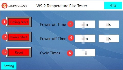
그림 4
3.2 매개변수 설정 페이지
① Setting the duration of power application to the sample; ② Setting the duration of power disconnection from the sample; ③ Setting the number of repetitions; ④ Setting the duration of the alarm.
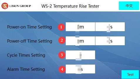
그림 5
4. 시험 전 준비 사항
4.1 환경 준비
표준 요구 사항에 따라 테스트 어셈블리는 테스트 중 공기 흐름이 온도 측정 정확도에 영향을 미치는 것을 방지하기 위해 통풍이 없는 환경에 배치해야 합니다.
When testing flush-mounted electrical accessories, a test environment that complies with the standards must be set up in advance (see the model in the “General Accessories” section): Place the mounting box into the pine trough and fill the space between the mounting box and the trough with plaster, ensuring that the front edge of the mounting box is flush with the front surface of the pine trough (with a deviation of no more than ±5 mm). The plaster should be 10 mm to 15 mm thick, and the pine trough must have at least 25 mm of wood surrounding the plaster; After the test assembly is constructed, it must be allowed to dry for at least 7 days.
Note: If you need models in other sizes, please contact us or manufacture them yourself according to the specifications.
4.2 Confirmation of Standards Used
4.2.1 시험 매개변수 결정
시험 대상 시료의 종류에 따라 해당 표준을 참조하여 주요 매개변수를 확인하십시오.
| 샘플 유형 | 표준 시편 | 테스트 전류 | 시험 기간 | 온도 상승 한계 |
| 콘센트/플러그 | GB / T 2099.1-2021 | 표 20에 명시된 대로 (예: 멀티 콘센트의 경우 해당 정격 전류를 사용하십시오) | 60 ± 5분 | 단자, 커넥터 및 클램핑 부품 ≤ 45K |
| 스위치 | GB 16915.1-2024 | As specified in Table 17 (e.g., 20 A test current for a 16A circuit breaker) | 1h | 단자 ≤ 45K; 비금속 손잡이/핸들 ≤ 5K; 기타 비금속 외부 부품 ≤ 55K; 금속 손잡이/핸들 ≤ 35K; 기타 금속 외부 부품 ≤ 45K |
| 커넥터 | GB / T 13140.1-2008 | 표 2에 명시된 대로 (예: 2.5mm² 연결 용량의 경우 24A의 시험 전류) | 열평형 상태에 도달한다(1시간 이내 온도 상승 ≤ 1K). | 고정부의 전류 전달 성분 ≤ 45K |
| Note: For switches with indicator lights, if the circuit current is ≤3 mA (neon lamp/LED), temperature rise tests related to the indicator light may be omitted; when testing protective devices (such as fuses), use low-impedance wire to short-circuit the circuit. | ||||
4.2.2 테스트 모드의 유효성 검증
부하/무부하 사이클 테스트가 필요한지 여부를 판단하십시오(관련 표준 요구 사항 참조). 사이클 테스트가 필요한 경우 사이클 수, 각 전원 켜짐 기간 및 각 전원 꺼짐 기간의 지속 시간을 명시하십시오.
Verify the temperature measurement method (this device uses a thermocouple for measurement) and ensure that the thermocouple is positioned so as not to affect measurement accuracy (e.g., near critical areas such as clamping components or terminals).
4.3 샘플 준비
4.3.1 시료 선택 및 준비
Select representative samples (such as plugs, receptacles, switches, terminal blocks, etc.) based on the test requirements, ensuring that the samples are in good condition, free of damage, and consistent with the product’s condition upon shipment;
Electrical accessories with detachable wiring must be connected to polyvinyl chloride (PVC)-insulated wires with the corresponding rated cross-sectional area as required by the standard (see the table below); accessories with non-detachable wiring shall be tested as delivered;
온도 상승 시험에 사용되는 구리 도체의 공칭 단면적(GB/T 2099.1-2021 참조):
| 정격 전류 (A) | 고정형 전기 액세서리 | 휴대용 전기 액세서리 |
| ≤ 10 | 단선/연선 1mm² | 유연 전선, 1.5mm² |
| >10 및 ≤16 | 단선/연선 1.5mm² | 유연 전선, 2.5mm² |
| > 16 | 단선/연선, 4mm² | 유연 전선, 6mm² |
단자 나사 또는 너트는 지정된 토크의 2/3로 조여야 합니다(GB/T 2099.1-2021 표준의 요구 사항 12.2.8 참조).
4.3.2 샘플 설치
매립형 콘센트: 소나무 홈에 매립하고 필요에 따라 석고로 채운 매립형 박스에 설치합니다. 케이블은 박스 상단을 통해 들어가며, 공기 순환을 방지하기 위해 입구를 밀봉합니다. 박스 내부의 각 도체의 길이는 (80±10) mm입니다.
Surface-mount outlets/switches: Mounted at the center of a pine block, which must be at least 20 mm (thick) × 500 mm (wide) × 500 mm (high);
Plug: Place it in the center of a pine block (block specifications as above); if the plug has a side grounding prong or a spring-loaded grounding prong, it must be inserted into a standard fixed outlet for testing;
다수의 고정 콘센트(공용 단자): 가장 불리한 조건에서 테스트 플러그를 삽입하여 테스트 전류 분배가 요구 사항을 충족하는지 확인하십시오.
커넥터: 단극 단자는 미리 정해진 방식에 따라 전선을 연결하고, 다극 단자는 최대 3개의 인접한 단자를 연결합니다. 전선 길이는 표준 요구 사항을 준수해야 합니다(전선 굵기 10mm² 이하인 경우 1m, 10mm² 초과인 경우 2m, 제조업체 사양에 따라 길이를 단축할 수 있음).
4.4 Equipment Preparation
4.4.1 샘플 연결
Connect the components in series in the direction indicated by the black lines in the figure below. When the load current is high, use sufficiently thick connecting wires to ensure that the wires’ current-carrying capacity matches the test current and to prevent the wires from overheating.
If connecting only one sample, connect terminals ① and ⑨; if connecting two samples in series, connect the first sample to terminals ① and ②, and the second sample to terminals ② and ⑨; If you need to connect three samples in series, connect the first sample to terminals ① and ②, the second sample to terminals ② and ③, and the third sample to terminals ③ and ⑨. And so on.
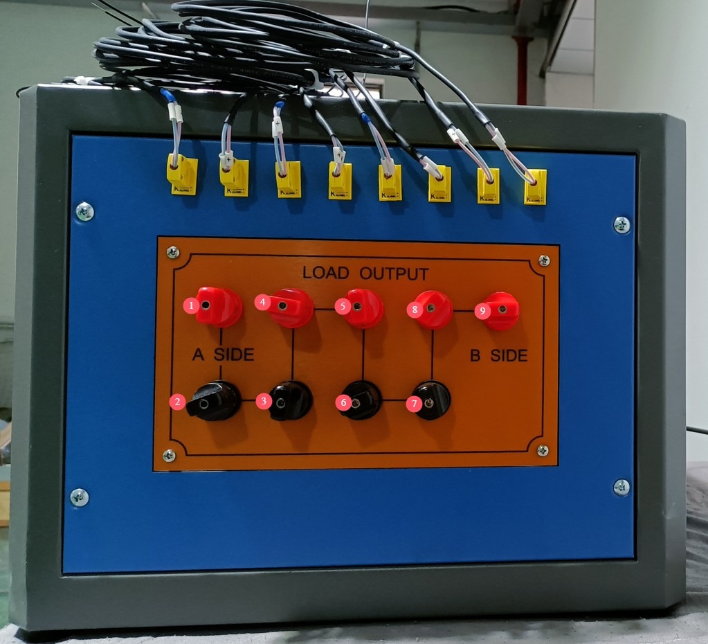
그림 6
매립형 콘센트를 예로 들면, 모든 전선이 연결되면 아래 이미지와 같은 모습이 됩니다. 회로의 테스트 전류를 발생시키려면 단자를 단락시켜야 합니다.
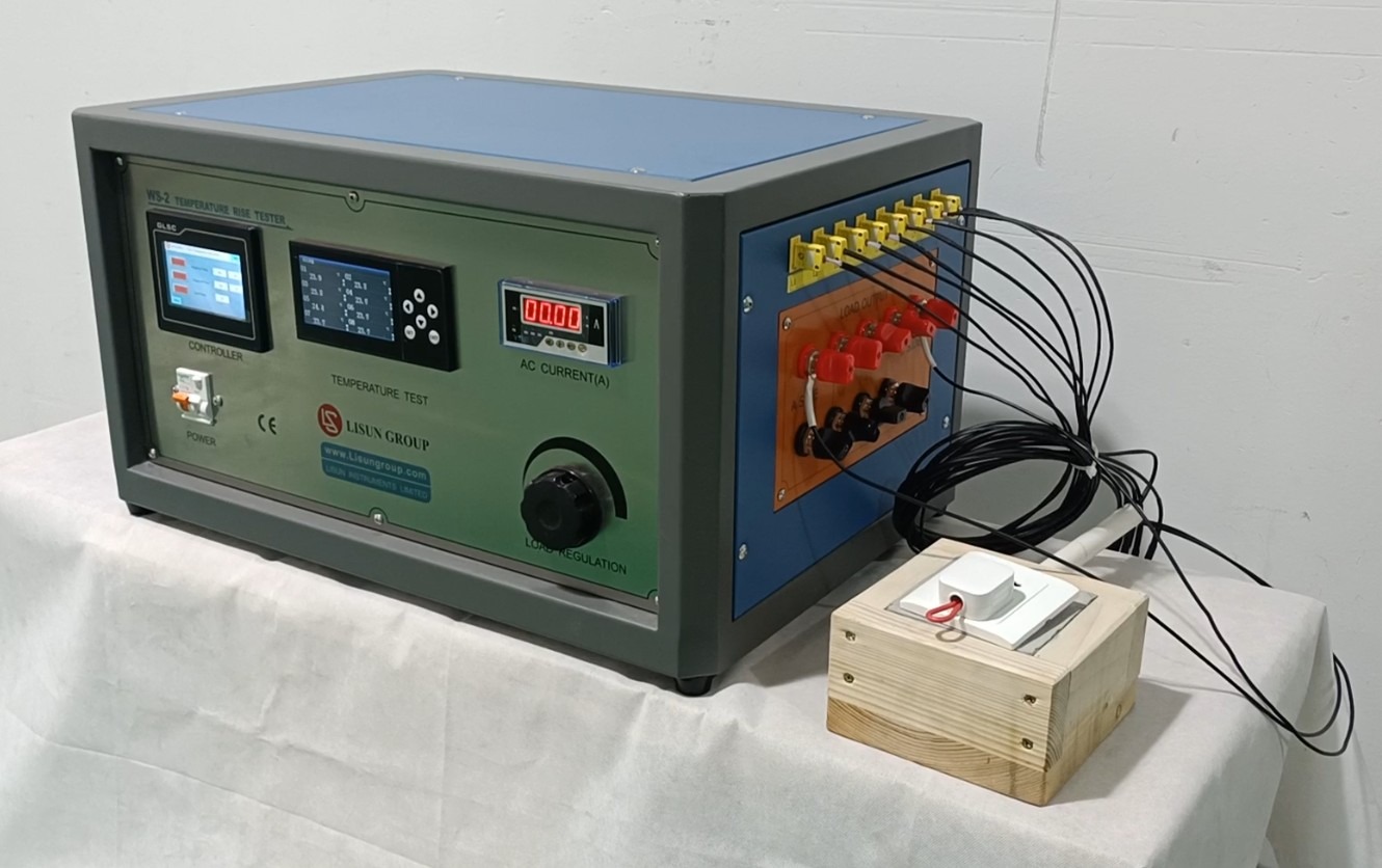
그림 7
참고: 샘플 설치 및 배선은 접촉 불량이나 아크 발생을 유발할 수 있는 느슨한 배선 연결을 방지하기 위해 표준 요구 사항을 준수해야 합니다.
Select the key points where temperature measurements are required (such as terminals, connectors, clamping components, and housings). Securely attach the other end of the thermocouple (the sensing end) to the measurement point using high-temperature-resistant tape or adhesive (such as Loctite 7452), ensuring tight contact with the sample surface and that it does not come loose.
4.4.2 장비 워밍업
To ensure safety, first turn the front-panel test current adjustment knob counterclockwise to the lowest setting. Then turn on the device’s power switch and let it warm up for 15 minutes. Proceed with the next steps only after the touchscreen display has stabilized and the temperature display shows no abnormal fluctuations.
5. Operating Procedures for the Temperature Rise Test
5.1 매개변수 설정
Access the touchscreen parameter settings interface and set the following: ① sample power-on time, ② sample power-off time, ③ number of cycles, and ④ alarm duration (the device will sound an alarm when the test is complete). Note: Please refer to the relevant standard requirements to determine whether the test requires a power-on/power-off cycle and how long the test should last. After completing the settings, click “Test” to return to the test interface.
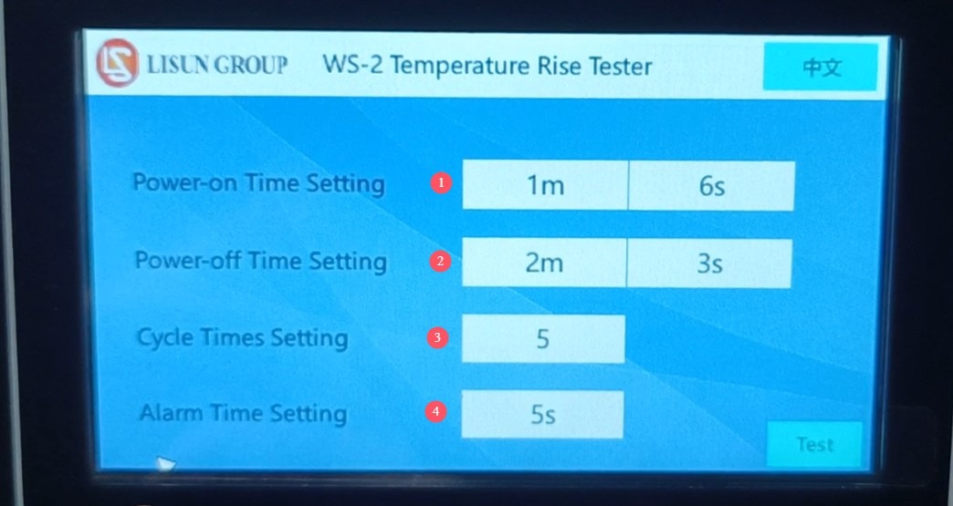
그림 8
5.2 Commissioning: Current Testing and Startup Testing
① Tap “Test Power-On” on the touchscreen, ② turn the load current adjustment knob, and ③ adjust the real-time current displayed here to meet the test requirements (please refer to the applicable standard to determine the specific current required).
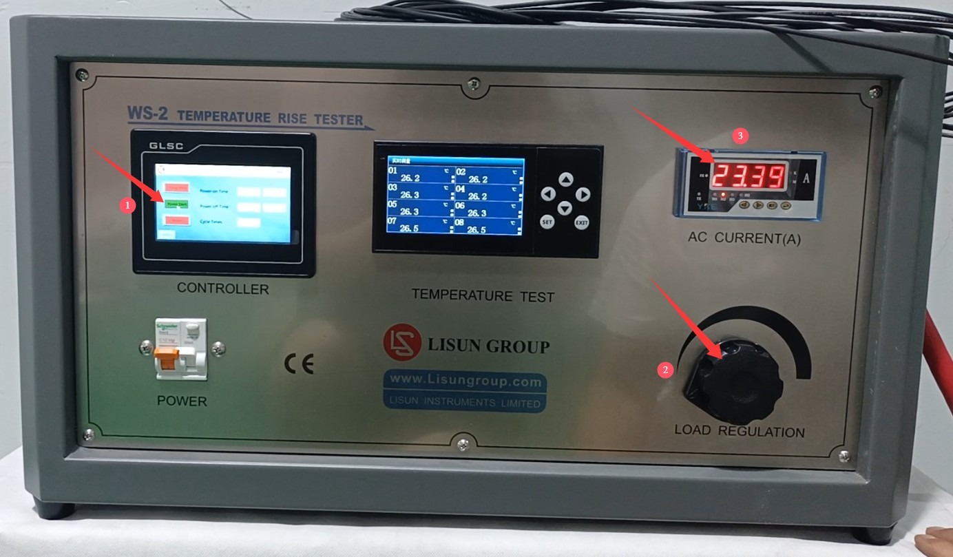
그림 9
Note: Adjust the current gradually to avoid sudden spikes or drops that could damage the equipment or the sample.
Once the test current has stabilized (fluctuation range ≤ ±0.5%), click “Start Timer” to begin the test. During the test, monitor the displayed temperature to determine whether the sample has passed the test.
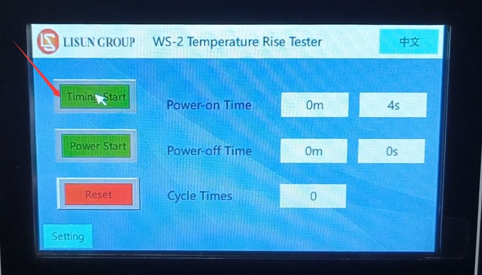
그림 10
Temperature data must be closely monitored during the test. If an abnormal spike in temperature or an alarm occurs, the test should be stopped immediately to investigate any issues with the sample or equipment.
5.3 Monitoring the Test Process
Monitor the temperature data on the display in real time, and record the initial temperature (when the power is off) and temperature changes during the test;
Monitor the load current display to ensure that the current remains stable within the test current range at all times. If abnormal fluctuations in the current occur, promptly investigate the cause (such as loose connections or poor contact with the sample);
If there is an abnormal spike in temperature or an alarm is triggered, the test should be stopped immediately to investigate any issues with the sample or equipment.
During the test, do not alter parameters, touch the wiring, or move the sample without authorization to ensure stable test conditions.
6. 테스트 후 절차
6.1 Equipment Operation
6.1.1 테스트 종료
After the test is complete, wait for the device to automatically cut off the test current, or manually click “Start Test Power” again to cut off the test current;
터치스크린의 "재설정" 버튼을 눌러 이 테스트의 데이터를 삭제하고 기기를 초기 상태로 복원하세요.
Slowly turn the test current adjustment knob counterclockwise to the lowest position, then turn off the device’s power switch.
6.2 데이터 처리
6.2.1 데이터 기록
시험 전후의 온도 데이터(초기 온도, 최종 온도 및 최대 온도 상승)를 기록하고 다음 공식을 사용하여 온도 상승을 계산하십시오. 온도 상승(K) = 최종 온도(°C) – 초기 온도(°C);
Record the test current, test duration, number of cycles (if applicable), sample model, serial number, and test environment parameters (temperature, humidity), and compile this information into a test record form.
6.2.2 결과 해석
Comparison of Temperature Rise Data from Comparative Tests with Standard Limits:
① If the temperature rise is ≤ the standard limit, the sample is deemed to meet the temperature rise requirement;
② If the temperature rise exceeds the standard limit, the sample is deemed nonconforming, and the cause of the nonconformity must be analyzed (e.g., the connector sleeve is too thin, poor contact, insufficient wire cross-sectional area, etc.).
6.3 Sample and Equipment Preparation
6.3.1 시료 채취
After the sample has cooled to room temperature, remove the load wires and thermocouples one by one. When removing them, avoid pulling on the wires with force to prevent damage to the sample or the thermocouples;
시험 후 시료의 상태를 검사하고(예: 변형, 그을림 또는 연결 부위의 느슨함 여부) 관련 세부 사항을 기록하십시오.
6.3.2 장비 구성
열전대와 전선 등의 부속품을 정리하고, 전선이 엉키거나 손상되지 않도록 깔끔하게 보관하십시오.
Clean the surface of the equipment (wipe with a dry cloth; do not get it wet), remove any debris from the test area, and keep the environment tidy.
7. 일상적인 유지 관리 및 관리
7.1 Short-Term Storage Requirements
장비를 매일 사용하는 경우, 각 테스트 후 청소가 완료되면 추가 조치는 필요하지 않습니다.
7.2 장기 보관 요건
기기를 장기간(한 달 이상) 사용하지 않을 경우 모든 케이블을 분리하고 먼지가 쌓이는 것을 방지하기 위해 먼지 덮개로 기기를 덮어주십시오.
The device should be powered on once a month for just half an hour to prevent the aging of electrical components (such as capacitors and contactors).
8. 문제 해결 및 일반적인 문제 해결 방법
8.1 The device won’t turn on
8.1.1 실패 원인
전원 코드가 제대로 연결되지 않았거나 손상되었습니다. 전원이 공급되지 않거나 전압이 비정상적입니다. 기기의 퓨즈가 끊어졌습니다. 전원 스위치가 오작동합니다.
8.1.2 치료 방법
Check that the power cord is securely connected, the plug is firmly inserted, and the power cord is not damaged; if damaged, replace it. Use a multimeter to verify that the supply voltage is AC 220 V ± 10%; if there is no power, troubleshoot the power circuit; Check whether the fuse has blown; if so, replace it with a fuse of the same specification (never substitute with other conductors). If none of the above issues are found, the power switch may be faulty; contact the manufacturer for repair.
8.2 The current cannot be adjusted or is unstable
8.2.1 실패 원인
부하 전류 조절 노브가 손상되었거나, 시료 리드 연결부가 헐거워졌거나 접촉 불량이거나, 전압 변압기가 고장났거나, 시료 배선이 잘못되었거나, 시료 자체에 결함이 있는 경우(예: 개방 회로)가 발생할 수 있습니다.
8.2.2 치료 방법
Check whether the knob rotates smoothly without any sticking; if damaged, replace it. Re-inspect the sample wiring, tighten any loose connections, check for short circuits, and replace any damaged sample wires; Disconnect the sample wiring and directly short-circuit the device’s sample terminals. If the current still cannot be adjusted or remains unstable, the Voltage Transformer may be faulty; contact the manufacturer for repair. Check whether the sample wiring meets the requirements and whether the sample is functioning properly (e.g., no open circuits). Replace any faulty samples and try again.
8.3 Inaccurate temperature measurement or no display
8.3.1 실패 원인
The thermocouple is not connected properly or is damaged; there is poor contact between the thermocouple and the sample surface; the temperature measurement module is malfunctioning; the display shows an error.
8.3.2 치료 방법
Check whether the thermocouple is securely connected to the device interface; try unplugging and replugging it. If the thermocouple is broken or the insulation is damaged, replace it; Check whether the thermocouple’s sensing tip is in close contact with the sample; reattach it securely to ensure it is not loose; compare the measurement with a standard thermometer. If the deviation is too large, the temperature measurement module may be faulty; contact a calibration or repair service. If a single temperature channel shows no display, the interface for that channel may be faulty; try testing by switching to a different thermocouple interface.
8.4 Equipment Alarm Anomalies
8.4.1 오작동의 원인
온도 상승이 설정된 한계를 초과했습니다. 테스트 시간이 경과했습니다. 비정상적인 전류(과부하)가 발생했습니다.
8.4.2 치료 방법
If a temperature rise exceeds the limit and triggers an alarm: Immediately stop the test, check whether the sample is in good condition, whether the thermocouple is positioned correctly, and whether the test parameters comply with the standard; after troubleshooting, repeat the test. If a time-out alarm is triggered: This is a normal occurrence; proceed according to the test completion procedure. If an abnormal current alarm is triggered: Check whether the current setting exceeds the rated value; after troubleshooting, reset the equipment;