
 영어
영어 中文简体
中文简体 Русский
 Español
 Português
 Türkçe
 العربية
 Deutsch
 Polski
 Italiano
 Français
 한국어
한국어 ไทย
ไทย Tiếng Việt
 日本語
日本語





























바늘 화염 테스트
사용자 설명서
적용 할 수있는 LISUN 모델: ZY-3,ZY-3S
1. Unboxing and Basic Understanding of the Equipment
1.1 주요 기술 사양
| LISUN 모델 | ZY-3 | ZY-3S |
| 제품명 | 주택과 함께 | Without a case |
| 버너 각도 | Adjustable; tilted at 45° during testing; vertical during flame height calibration | |
| 연소가스 | ≥95% 부탄(선택 사양 전자 가스 유량계) | |
| 온도 측정 범위 | 0-1000 ° C | |
| Requirements for Increasing Flame Temperature | Heated from 100°C ± 2°C to 700°C ± 3°C in 23.5 s ± 1 s | |
| Thermocouples for Temperature Measurement | Φ0.5 mm Type K | |
| Number of Ignition Attempts per Test | Can be set for single or multiple consecutive ignitions | |
| 본체 재질 | High-temperature spray-coated steel structures are heat-resistant and corrosion-resistant, making them suitable for long-term high-temperature testing environments. | |
| 작동 디스플레이 | Proprietary extra-large LCD touchscreen + clear indicator lights + remote control operation | |
| 중량(평량) | 무게 180kg | 무게 40kg |
1.2 Unboxing Inspection and Verification of Accessories
1.2.1 포장 해제 및 육안 검사
When unpacking the equipment, handle it gently to avoid scratching the exterior casing with sharp tools. After unpacking, first inspect the exterior of the main unit to ensure there is no visible deformation, dents, or peeling paint, and that the panel gauges and buttons are not damaged or loose. If you find any damage or deformation to the equipment or its accessories, do not power it on for use.
Open the test chamber door and check whether any internal components have come loose during shipping or if there are any other abnormalities.
If you notice anything unusual, please contact us promptly.
1.2.2 본체 및 부속품
Needle Flame Test Main Unit: 1 unit.
Standard accessories include: ① Exhaust pipe, ② Copper block and thermocouple, ③ Silk paper, ④ Remote control, ⑤ Gauge, ⑥ Sample tray, ⑦ Igniter, ⑧ Stainless steel hose clamp (for securing the exhaust pipe), ⑨ Spare needles, spare fuses;⑩ Power cord, ⑪ Gas supply unit, ⑫ Butane gas.
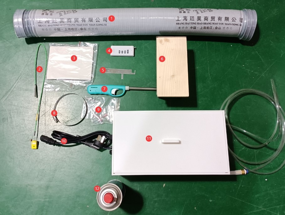
그림 1
Note: Butane gas and batteries are classified as hazardous materials and may not be shipped with the product. Please purchase compliant gas on your own for testing purposes. If you need to use a remote control, please also purchase batteries specifically designed for the remote control.
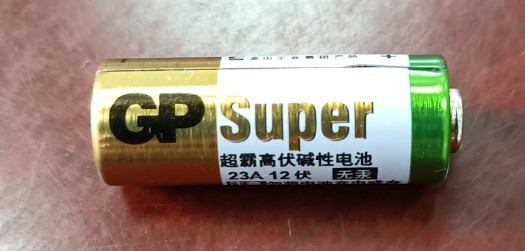
그림 2
The remote control has the same functions as the touchscreen buttons; users can choose whether or not to use the remote control.
Note: Download links for the electronic user manual, warranty card, and other documents have been sent via email. Please download them promptly. If you missed the email, you may contact us directly to request the download links again.
1.3 장비 구조 설명
1.3.1 시험 챔버의 정면도
① Touchscreen; ② Power controls, circuit breaker, and power on/off buttons; ③ Butane gas flow meter; ④ Test chamber door.
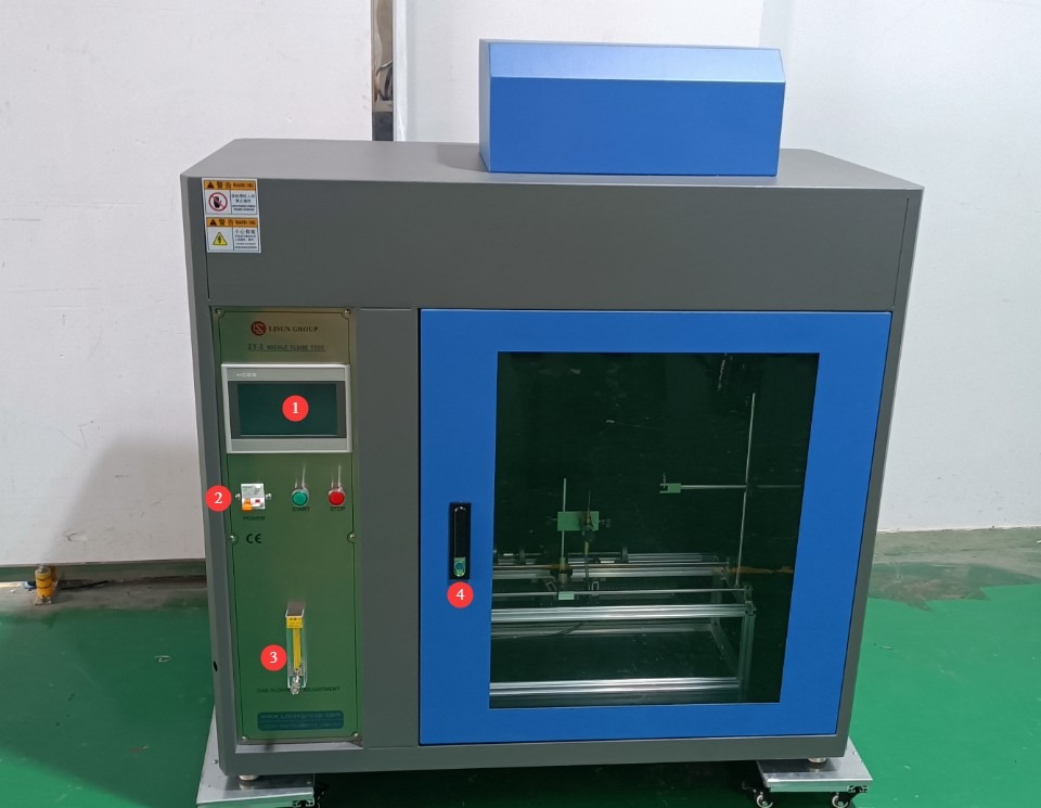
그림 3
1.3.2 시험실 후면
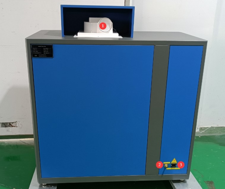
그림 4
① Exhaust vent, 100 mm in diameter, securely connected to an exhaust pipe that extends to the outdoors; ② Butane inlet; ③ Power cord receptacle.
1.3.3 Inside the Test Chamber
① Needle-flame burner, with adjustable height and angle; ② Sample holder, with adjustable position to meet different testing requirements; ③ Omega Type K thermocouple connector; ④ Thermocouple compensation lead.
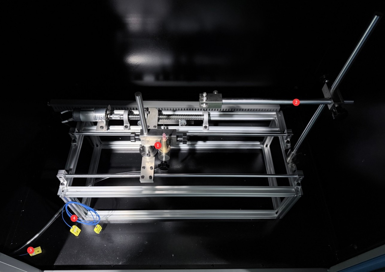
그림 5
Note: These are required when measuring the temperature rise in steps ③ and ④.
2. 안전상의 주의
2.1 전기 안전
2.1.1 전원 연결
220V single-phase power; power outlets must comply with safety standards, provide proper grounding, and have a rated current that matches the equipment’s power rating (it is recommended to install a dedicated circuit breaker).
2.1.2 접지 사양
The equipment must be reliably grounded, with a grounding resistance of ≤4 Ω. Do not use gas lines, non-metallic water pipes, or neutral wires as substitutes for the grounding wire. After grounding is complete, use a Grounding Resistance Tester to measure the grounding resistance. Power may only be applied after confirming that the resistance meets the requirements, to prevent electric shock, equipment malfunction, or measurement errors caused by poor grounding.
2.1.3 Contraindications for the Procedure
Before wiring, inspecting, or maintaining equipment, the main power supply to the equipment must be disconnected, and operation may only begin after confirming that there is no residual voltage;
감전 위험을 방지하기 위해 젖은 손으로 장비의 전원 스위치, 터치스크린 또는 계기판 버튼을 조작하지 마십시오.
전기 제어 캐비닛 내부에는 먼지나 이물질이 들어가 단락을 일으키거나 부품을 손상시킬 수 있으므로 공구나 종이 등의 이물질을 넣지 마십시오.
장비가 작동 중일 때는 전원 코드나 신호 케이블을 연결하거나 분리하지 마십시오. 단락으로 인해 컨트롤러 또는 전기 부품이 손상될 수 있습니다.
2.2 작동 안전
2.2.1 작동 안전
While the equipment is in operation, non-professionals are prohibited from disassembling or repairing it. In the event of a malfunction, contact after-sales service personnel or operate the equipment under the guidance of a technician;
The High Temperature Chamber door must be closed during testing. Observe the test process through the chamber viewing window to avoid burns from high-temperature radiation or sparks from burning materials;
In the event of a malfunction or abnormality, immediately stop the test and troubleshoot the problem (see “Chapter 9: Troubleshooting and Handling Common Malfunctions”). Do not force the equipment to start up; operating the equipment before the problem is resolved may cause further damage to the equipment.
2.2.2 금지된 행위
Do not use butane gas with a purity lower than 95% to avoid affecting flame stability and test accuracy;
Do not open the control cabinet door while the equipment is running to avoid touching internal high-voltage components and causing an electric shock;
Do not disassemble core components without authorization; modifying the equipment will void the warranty and may result in safety incidents;
Do not place heavy objects (such as tools or accessories) on top of the equipment to avoid damaging the equipment panel or impeding heat dissipation;
Do not stack flammable items (such as cardboard boxes, plastic wrap, etc.) around the equipment.
2.3 환경 안전
2.3.1 설치 요구 사항
The equipment must be installed in an air-conditioned room where the ambient temperature is maintained between 5°C and 25°C and the relative humidity is ≤85%. If the ambient humidity is high, condensation may form near the equipment door and test ports; in such cases, improve room ventilation or use a dehumidifier;
The installation site must be free of high concentrations of dust, corrosive gases (such as sulfur dioxide and chlorine), and flammable or explosive atmospheres. Direct sunlight must not be allowed to shine on the equipment to prevent corrosion of the equipment housing and deterioration of electrical components;
The storage of flammable and explosive materials (such as alcohol, gasoline, etc.) is strictly prohibited in the test area to prevent the risk of fire or explosion;
Butane gas is a highly flammable substance. Store it at a temperature of ≤40°C, and keep it away from direct sunlight, violent impacts, and sources of fire;
The work area is equipped with fire extinguishers (dry powder or carbon dioxide types), and operators are familiar with how to use them;
Keep the equipment away from areas with significant fluctuations in ambient temperature, such as near ventilation ducts and room entrances, to prevent these fluctuations from affecting the equipment’s temperature control accuracy;
Stay away from sources of strong magnetic and electric field interference (such as large electric motors and high-voltage equipment).
2.3.2 공간 요구 사항
The distance between the equipment enclosure and the wall, as well as surrounding structures (such as other test equipment and shelving), must be at least 1000 mm to facilitate maintenance;
At least 2000 mm of space must be left at the equipment door opening to ensure that the door can be opened in any direction, facilitating the placement and removal of samples.
2.3.3 Horizontal Placement
The device must be placed on a flat surface. Use a level to ensure the device is level: Place the level on the top surface of the device and make sure the bubble is centered. Note: The device has four adjustable legs that can be used to level it. Once leveled, ensure that all four legs are firmly in contact with the surface.
If the equipment is tilted, it will cause the needle flame burner to be misaligned and may result in the displacement of the sample, burner, temperature-rising copper block, and other components, thereby affecting the test results.
2.4 기타
For any matters not covered in this manual, please proceed with caution or contact us.
3. 터치스크린 프로그램 소개
3.1 사용자 인터페이스
① Burn time; ② Afterglow time; ③ Number of burns; ④ PV is the current value; ⑤ SV is the set value; ⑥ Lighting: Turns on the lighting inside the test chamber to facilitate observation; ⑦ Fan: Expels smoke generated inside the test chamber after the test is complete; ⑧ Start (A): Starts the test;⑨ Reset (B)—click after the test is complete or before the next test begins to clear the test data; ⑩ Afterglow Pause (C)—used to record the time it takes for the sample’s afterglow to extinguish;⑪ Gas On (D), controls the opening and closing of the gas solenoid valve; ⑫ Parameter Settings, enters the parameter settings interface; ⑬ Test Records, views historical test data; ⑭ Temperature Calibration, performs a temperature rise test. Note: The four buttons (A, B, C, D) can also be controlled using a remote control.
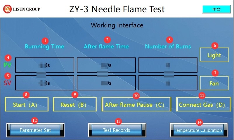
그림 6
3.2 파라미터 설정 인터페이스
① Burn time setting; ② Afterglow time setting; ③ Number of burns setting.
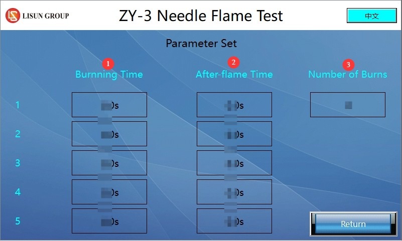
그림 7
Note: If only one burn cycle is required, set the number of burn cycles to 1. If a continuous burn test is required in accordance with a specific standard (such as IEC 62368-1:2023 Annex S S.1), set the number of burn cycles according to the standard; you must also set the burn time and afterglow time separately for each burn cycle.
3.3 Test Record Interface
① Recorded burn time; ② Recorded afterglow time; ③ Reset—tap to clear the data on this page.
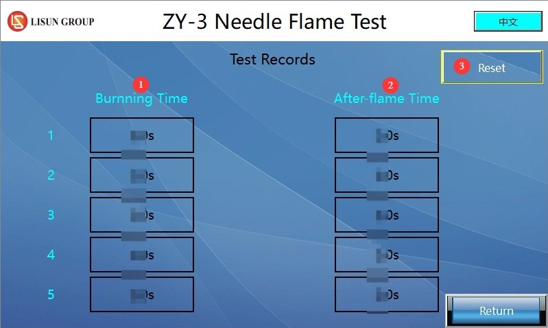
그림 8
Note: Whether conducting a single-burn test or a continuous-burn test, the system automatically records the burn time and afterglow time for each burn. It can store data for up to 5 burns; once the limit is reached, you must press the reset button to clear the data before continuing to record.
3.4 Temperature Calibration Interface
① Current temperature display; ② Temperature rise time display; ③ Start temperature setting; ④ End temperature setting; ⑤ Temperature correction (no changes needed); ⑥ Reset: Tap to clear the current data and retest the temperature rise time.
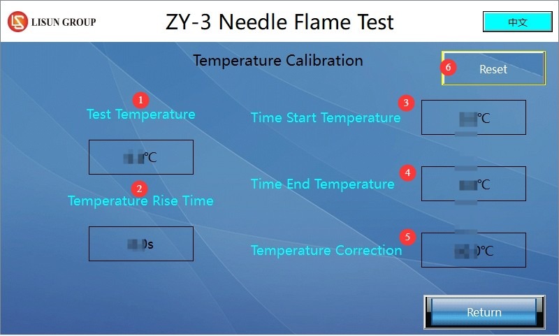
그림 9
Note: Common standards (IEC 60695-11-5, IEC 60695-2-2, GB/T 5169.5, etc.) require that the starting temperature for temperature rise tests be 100°C and the ending temperature be 700°C. Users may also set other starting and ending temperatures in accordance with specific standards.
4. 시험 전 준비 사항
4.1 External Environment
Set the ambient temperature to 23±2°C and the relative humidity to 50±5% to prevent environmental factors from affecting the test results. Note: The temperature and humidity requirements for the equipment’s storage environment differ from those for its operating environment.
4.2 Flame Adjustment
4.2.1 Connecting the Butane Gas Supply
If you are using our standard gas supply unit, you will need to purchase a butane cylinder of the appropriate size and then connect it using the gas hose provided. ① Gas outlet on the supply unit; ② Gas inlet on the pin-flame device.
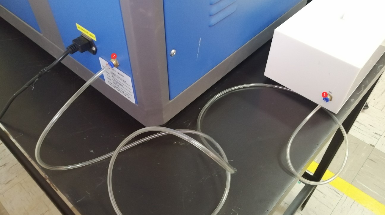
그림 10
① Lock the butane cylinder; ② Turn the knob to the maximum setting.
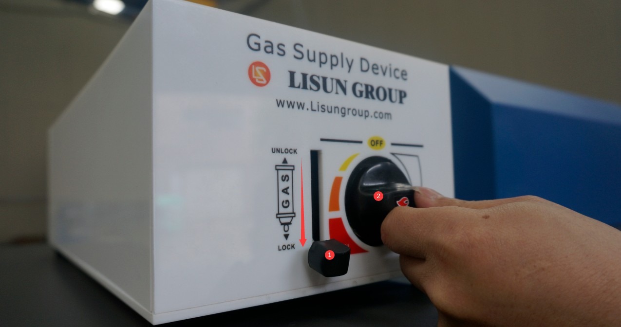
그림 11
You may also use any other air supply device; simply connect it to the device’s air inlet using a 6mm-diameter air tube.
4.2.2 Flame Adjustment
Adjust the burner nozzle to a vertical position.
Access the touchscreen program interface and tap the “Gas On (D)” button.
Adjust the gas flow meter knob and use the igniter to light the wick. If the gas flow is too high or too low, the wick may not ignite; in this case, continue adjusting the gas flow while attempting to ignite the wick until the flame ignites normally. Special Note: Minimize the time interval between turning on the gas and successful ignition (less than 5 seconds); otherwise, excess gas may accumulate inside the test chamber, creating a hazard during ignition.
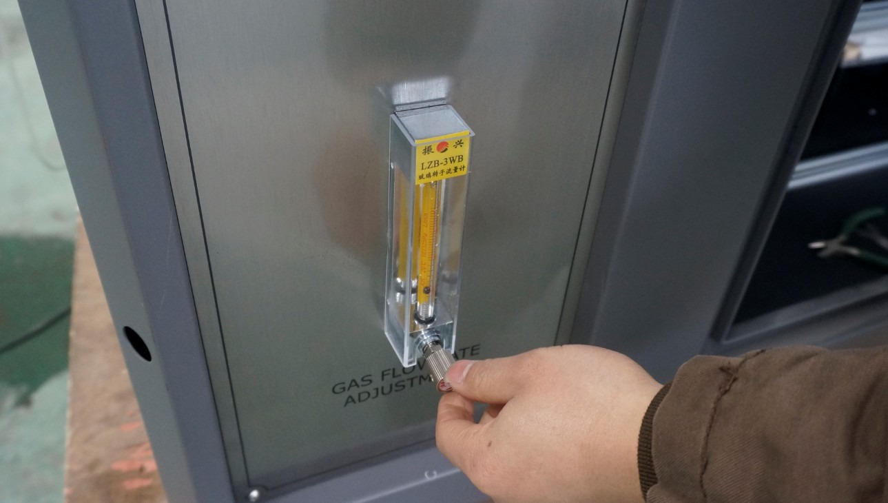
그림 12
Continue adjusting the flow meter knob and use a gauge to verify that the flame height meets the standard requirements. According to the standards (IEC 60695-11-5, IEC 60695-2-2, GB/T 5169.5, etc.), the flame height should be 12 mm.
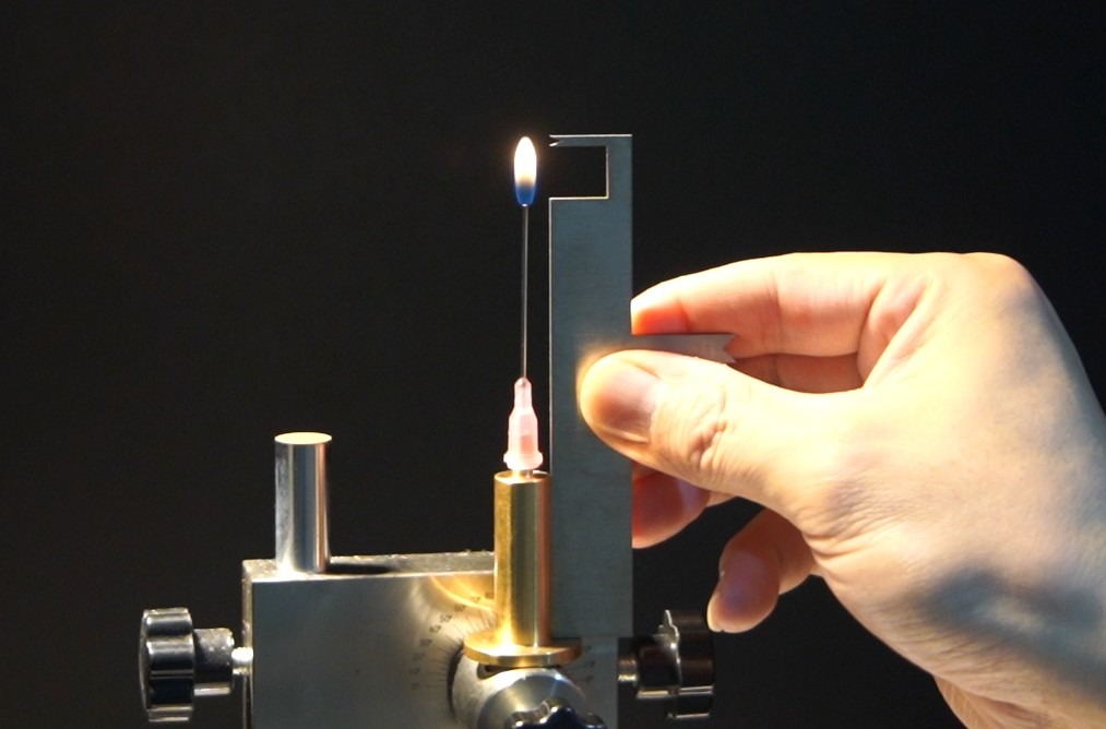
그림 13
Once the flame is adjusted, there is no need to adjust the flowmeter; simply tap the “Gas On” D button on the touchscreen to shut off the gas.
4.3 Sample Pretreatment and Sample Mounting
4.3.1 샘플 전처리
Test specimens must be complete equipment, assemblies, or components; if a portion of the specimen must be cut off, avoid exposing the cut edge to a flame.
The samples, pine boards, and silk paper should be left at 23±2°C and 50±5% relative humidity for at least 24 hours to ensure they are in a stable condition.
Remove oil, dust, and other contaminants from the sample surface to ensure that the test conditions match those of normal use.
4.3.2 샘플 설치
Adjust the needle to the test angle (45°) according to the standard and secure it in place.
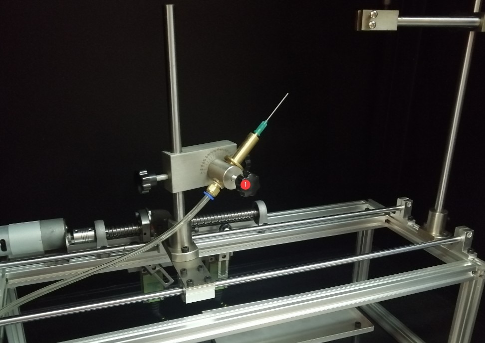
그림 14
Go to the work page. Click the “Start (A)” button. The burner will automatically move to the limit stop position. At this point, secure the sample based on the position of the needle.
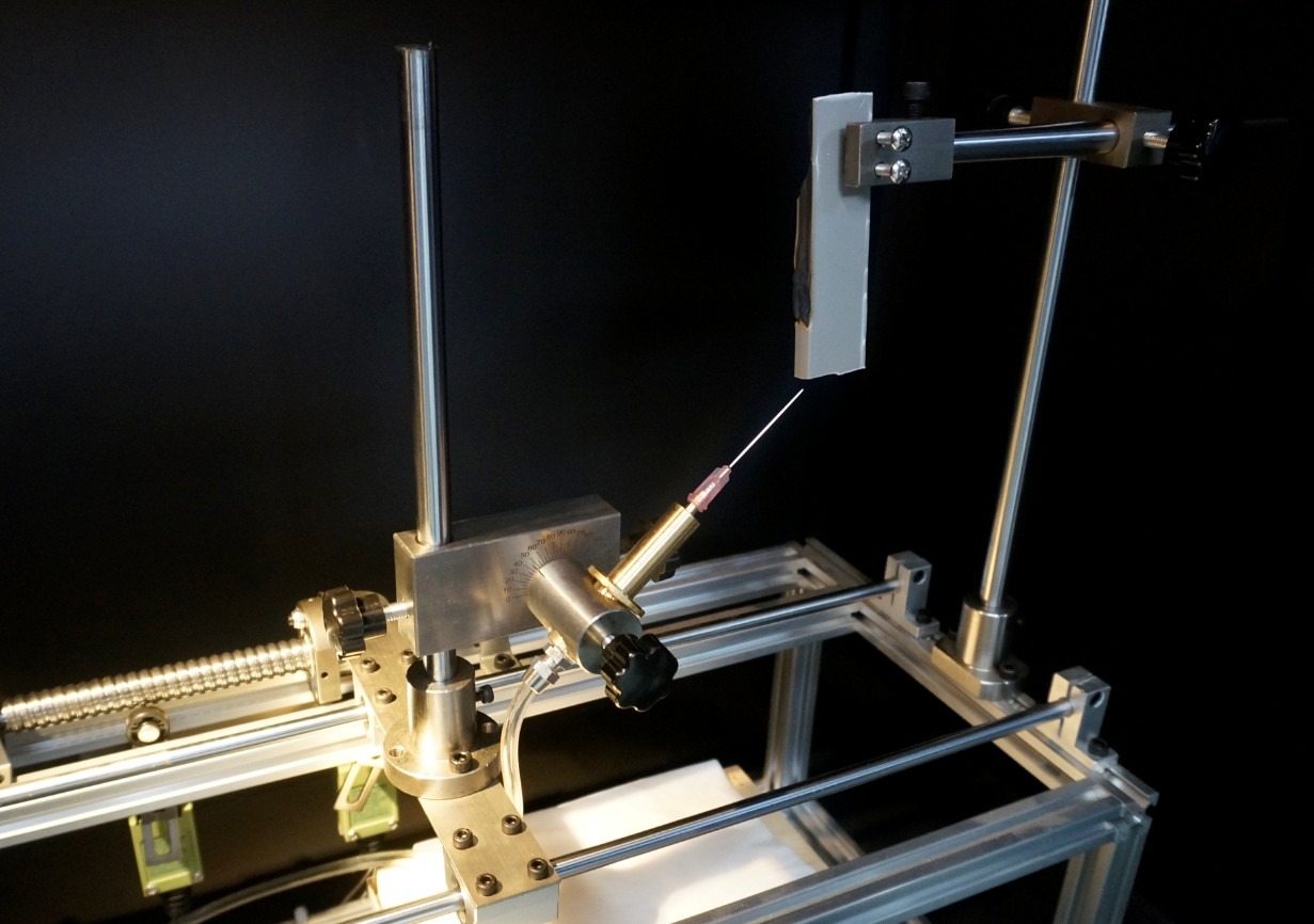
그림 15
According to standard IEC 60695-11-5, the flame application positions are as follows:
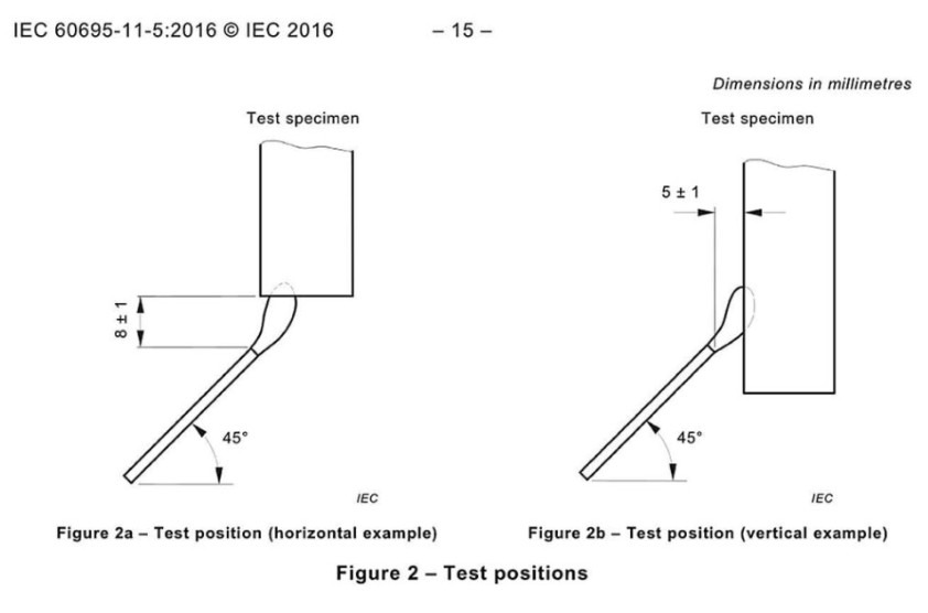
그림 16
Once the sample is securely in place, click the “Reset (B)” button to return the burner to its initial position. The burner will also automatically return to its initial position once the set combustion time has elapsed. Note: You must click the “Reset (B)” button once before you can click the “Start (A)” button again.
Place the silk paper on the sample holder and position the sample holder directly below the combustion point.
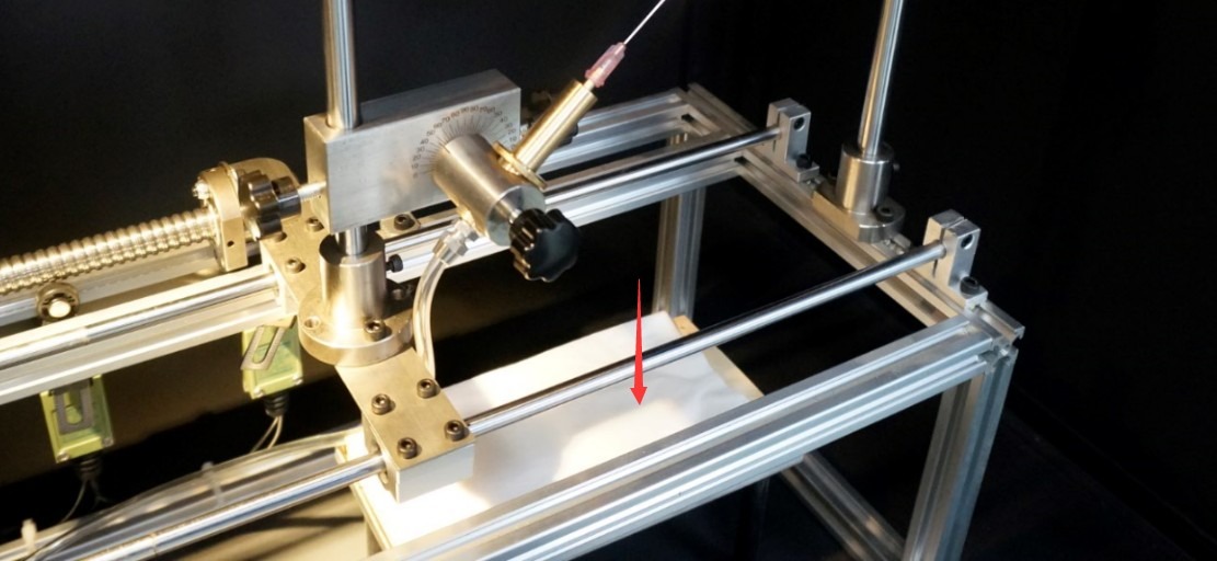
그림 17
5. Needle Flame Test Procedure
5.1 테스트 매개변수 설정
Set the combustion time, afterglow time, and number of combustion cycles based on the sample properties and standard requirements.
5.2 시험 절차
Press the “Gas On (D)” button on the touchscreen. Use the igniter to light the burner needle. Then close the test chamber door.
Click “Reset (B),” then click the “Start (A)” button to begin the test. The burner moves to the ignition position, and the burn time begins to be timed.
For a single combustion test: When the set combustion time ends, the afterglow time begins to be measured, the gas supply is automatically shut off, and the burner returns to its initial position. If the test specimen catches fire during the test, press the “Afterglow Pause (C)” button when the flame on the test specimen goes out to record the afterglow time.
For multiple combustion tests: At the end of the set first combustion time, the burner returns to its initial position, but the flame does not extinguish. If the sample’s flame does not extinguish within the set first afterglow time, the sample fails the test, and the gas supply is automatically shut off. If the sample’s flame extinguishes within the set first afterglow time, click “Afterglow Pause (C)” to end and record the data for the first ignition, and the burner will automatically return to the sample to start the timer for the second ignition. The third, fourth, and fifth flame application tests are conducted automatically using the same method.
6. 테스트 후 절차
6.1 Equipment Operation After Testing
6.1.1 안전 취급
After the test is complete, click the “Fan” button to activate the exhaust system and remove smoke and toxic gases from the chamber. Wait at least 5 minutes for the chamber to ventilate before opening the door.
Close the valve on the gas supply unit, unlock the gas cylinder, remove it, and store it as required (avoid direct sunlight and high temperatures, etc.).
6.1.2 장비 청소
After the equipment has cooled, wipe the inner walls of the test chamber, the burner nozzle, and the sample holder with a dry cloth to remove any combustion residues.
If the silk paper or pine board has been damaged by fire, replace it immediately.
Check to see if the burner nozzle is clogged; if there are any impurities, clean it with a fine needle (taking care not to damage the nozzle orifice).
6.2 Recording and Organizing Experimental Data
The test report must include the following:
Sample type, specifications, preparation methods, and pretreatment conditions;
Number of test specimens, installation locations, and flame application points;
Test parameters: burning time, afterglow time, number of tests;
Test Observations: Whether the sample ignites, the duration of the afterglow, and whether the sample is completely burned;
Test Results: Does it meet the flammability requirements (no ignition or afterglow ≤ 30 seconds, and the tissue paper does not ignite)?
6.3 샘플 준비
If samples are not completely incinerated after testing, they should be classified and disposed of as waste. If they contain toxic or flammable residues, they must be sealed and handed over to a specialized agency for disposal.
Retain a portion of the post-test samples for subsequent review or to verify the results.
6.4 장비 보관
6.4.1 단기 보관 요구 사항
If the equipment is for everyday use, no special handling is required.
6.4.2 Requirements for Long-Term Storage
If the device will not be used for an extended period (more than one month), please unplug the power cord and cover the device with a dust cover to prevent dust buildup.
The device should be powered on once a month for just half an hour to prevent the aging of electrical components (such as capacitors and contactors).
7. 온도 교정
7.1 Calibration Preparation
7.1.1 Calibration Conditions
Ambient temperature: 23±2°C; relative humidity: 50±5%; no airflow disturbances;
The calibration copper block and thermocouple are in good condition. The copper block is made of Cu-ETP UNS C11000 and weighs 0.58 g ± 0.01 g.
7.1.2 Basis for Calibration
According to the requirements of Annex A of IEC 60695-11-5 (GB/T 5169.5), the time required for the temperature of a copper block to rise from 100 °C ± 5 °C to 700 °C ± 3 °C is 23.5 s ± 1.0 s.
7.2 프로 시저
Adjust the flame to 12 mm ± 1 mm using the method described in Section 4.2, then extinguish the flame.
Insert the thermocouple plug into the Omega Type K thermocouple socket provided inside the test chamber. Secure it using the standard copper block so that it is positioned 6 mm directly above the burner nozzle, ensuring that the flame fully impinges on the copper block.
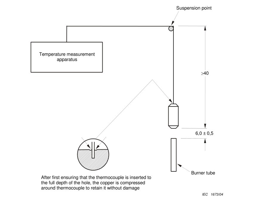
그림 18
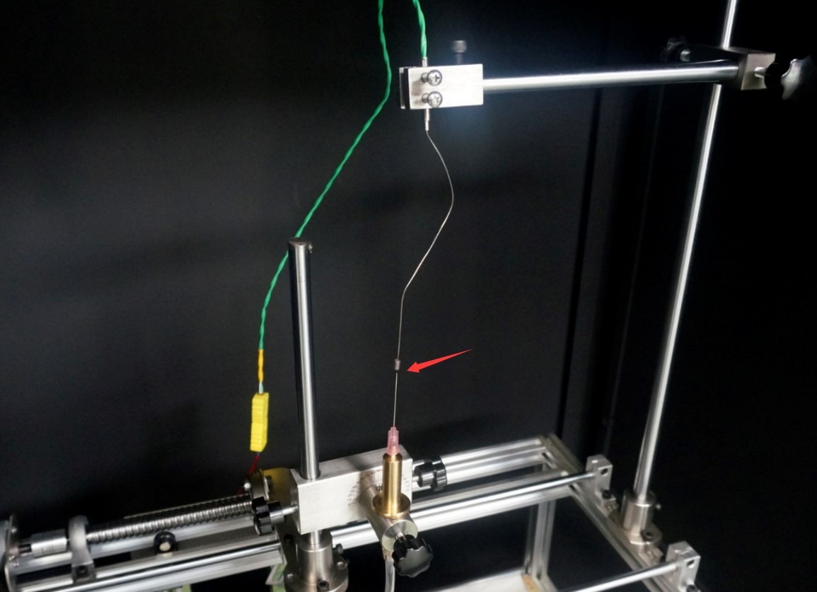
그림 19
Go to the temperature calibration screen and set the following: start temperature to 100°C, end temperature to 700°C, and leave the temperature correction at the default value. Click “Reset” to clear the historical data.
Return to the work interface, click “Gas On (D),” use the igniter to light the burner, and slowly close the test chamber door.
Return to the temperature calibration screen and observe the current temperature and heating time displayed on the touchscreen. The timer starts automatically when the copper block reaches 100°C and stops automatically when it reaches 700°C.
Repeat the calibration three times, allowing the copper block to cool naturally to below 50°C after each measurement.
Calculate the average time to temperature rise based on the three measurements; if it is within 23.5 s ± 1.0 s, the flame meets the requirements.
7.3 Handling Temperature Deviations During Calibration
The temperature rise time is used to determine whether the butane gas you are using, the flame being calibrated, and the test conditions meet the standard test requirements. If the temperature rise time is incorrect, it means your test does not meet the standard requirements; it does not indicate a problem with the equipment itself.
8. 일상적인 유지 관리
| 유지보수 주기 | 유지 관리 프로젝트 | 유지 보수 작업 |
| 각 테스트 후 | 장비 청소 | 1. Wipe down the interior and exterior of the test chamber, the observation window, and the fixtures; 2. Clean up any drips and soot from the sample tray. |
| 일주일에 한 번 | 베어링 유지 보수 | Wipe down the linear bearing rail with a cloth dampened with mineral oil to ensure the moving parts operate smoothly. |
| 한달에 한번 | Gas System Inspection | 1. Check the gas connection for leaks (using soapy water); 2. Inspect the hoses for signs of aging and replace them if necessary; |
| 3 개월에 XNUMX 회 | 불꽃 교정 | Flame temperature rise test to verify whether the temperature rise time complies with 23.5 ± 1 s |
| 6 개월에 XNUMX 회 | 전기 시스템 검사 | 1. Check that the power lines and ground terminals are secure; 2. Replace worn-out fuses; 3. Test the ignition system’s performance |
| 일년에 한번 | 종합적인 유지관리 | 1. Replace the gas hoses and gaskets; 2. Calibrate the touchscreen’s timing accuracy; 3. Inspect the needles for wear and replace them if necessary; 4. Contact the supplier to arrange for professional testing and calibration |
9. 문제 해결 및 일반적인 문제 해결 방법
9.1 The flame won’t ignite
| 결함 증상 | 가능한 원인들 | 순서 |
| No flame during ignition | 1. The valve on the gas supply unit is not open; 2. There is a leak in the gas line; 3. The needle is clogged; 4. The igniter is malfunctioning | 1. Open the gas supply valve and make sure there is sufficient gas; 2. Check the pipe connections, tighten any loose parts, and use soapy water to check for leaks; 3. Use a fine needle to remove debris from the needle tip, or replace it with a spare needle; 4. Replace the igniter battery, or replace the igniter with a spare one |
| Gas is escaping, but it won’t ignite | 1. Insufficient gas purity; 2. Excessive gas buildup inside the test chamber; 3. The igniter is too far from the needle | 1. Replace the butane/propane gas with a purity of ≥95%; 2. Open the chamber door to ventilate for 5–10 minutes before igniting; 3. Adjust the position of the igniter so that it is close to the tip of the needle when igniting. |
9.2 Temperature Calibration Failed
| 결함 증상 | 가능한 원인들 | 순서 |
| The warm-up time is too long | 1. Insufficient flame height; 2. Gas flow rate too low; 3. Copper block misaligned | 1. Readjust the flame height to 12 mm ± 1 mm; 2. Turn the gas flow meter knob clockwise to increase the gas flow rate; 3. Adjust the position of the copper block to ensure it is 6 mm directly above the needle tip. |
| The warm-up time is too short | 1. Flame height exceeds the limit; 2. Gas flow rate is too high | 1. Reduce the gas flow rate and use a gauge to calibrate the flame height; 2. Fine-tune the flow meter knob to reduce the gas supply intensity. |
| No temperature display | 1. The thermocouple is not connected properly; 2. The thermocouple is damaged | 1. Unplug and replug the thermocouple connector to ensure a secure connection; 2. Replace the thermocouple with a new one. |
9.3 Afterglow duration cannot be recorded
| 결함 증상 | 가능한 원인들 | 순서 |
| After the sample flame goes out, clicking “Afterglow Pause” produces no response. | 1. The “Start” button was not pressed first; 2. The “Afterglow Pause” button was not reset; 3. Touchscreen malfunction | 1. Verify that the test has started and the burn time has elapsed; 2. Press the “Afterglow Pause” button to reset the system before proceeding; 3. Restart the device; if the problem persists, contact customer service. |
9.4 The Device Will Not Start
| 결함 증상 | 가능한 원인들 | 순서 |
| The touchscreen does not respond after the power is turned on | 1. The power cord is not properly connected; 2. The power supply voltage is abnormal; 3. The fuse has blown | 1. Check the power cord connection and make sure the plug is securely inserted; 2. Verify that the power supply voltage is 220V ± 10%; 3. Replace the fuse with one of the same specification (included in the packing list). |