추상
In industrial power grids and civil power supply systems, damped oscillatory ring‑wave interferences are generated due to high‑voltage switch switching, transformer transient oscillation, power faults and inductive load switching. Such transient disturbances couple into electrical and electronic equipment through power lines and signal lines, which may easily result in equipment crash, mis‑operation and even hardware damage. As key EMC test instrument, the ring wave simulator (ring wave generator) can reproduce real‑world ring‑wave interference under laboratory conditions. It performs immunity tests in accordance with GB/T 17626.12‑2023, IEC 61000‑4‑12 and other standards to evaluate the immunity capability of Equipment Under Test (EUT) against such interference, identify insulation weak points and circuit anti‑interference defects in a timely manner, and ensure stable operation of equipment in complex power environments. Taking the LISUN RWG61000‑12 series ring wave simulator as the research object, this paper describes the generation mechanism of ring‑wave interference, core functions of the simulator, key technical parameters and multi‑industry engineering application scenarios, so as to provide references for practical ring‑wave immunity EMC testing.
개요
Modern electrical and electronic equipment is widely applied in industrial control, new‑energy charging piles, medical devices, household appliances, power meters and other fields. Their power‑supply environments are filled with various transient electromagnetic disturbances. The ring wave is a non‑repetitive damped oscillatory transient pulse, which commonly exists in low‑voltage AC power‑supply networks. When high‑voltage switches operate, transient oscillation occurs in transformer windings, large‑scale motors start‑stop or short‑circuit faults take place in power systems, travelling‑wave reflection will be triggered by line impedance mismatch, generating steep‑rising, high‑amplitude and gradually attenuated 100 kHz oscillatory pulses, namely ring‑wave interference.
Such interference couples into equipment through power and signal cables and impacts power loops and signal interfaces. Many devices work normally under ideal laboratory power supply conditions, yet frequently suffer control anomalies, communication interruptions and functional disorder after being put into on‑site power grids. A large number of such failures are rooted in ring‑wave disturbance. To avoid equipment failure risks caused by on‑site electromagnetic environments, products are required to complete standardized ring‑wave immunity tests during R&D and type‑approval stages. The ring wave simulator serves as the core hardware for such tests. It can reproduce standardized ring‑wave waveforms in laboratories independent of complex field conditions and realize repeatable and comparable immunity assessment to expose hidden design risks of products in advance, which is an indispensable test device for electromagnetic‑compatibility verification.
1 Working Principle and Core Functions of Ring Wave Simulator
The ring wave simulator, also known as ring wave generator, mainly consists of high‑voltage energy‑storage unit, pulse‑forming network, power‑amplifier module, Coupling‑Decoupling Network (CDN) and human‑machine interaction control system. Standard damped oscillatory waveforms are generated by LC oscillation circuits. After power amplification, pulse signals with specified voltage and current are output. The coupling‑decoupling network injects disturbance into the ports of Equipment Under Test, meanwhile isolating external mains supply to prevent test pulses from polluting power grid in reverse and guarantee test safety and waveform fidelity.
The core function of the ring wave simulator is to simulate ring‑wave interference encountered by electrical and electronic equipment in real‑world scenarios. It reproduces damped oscillatory pulses generated by high‑voltage switch operation, transformer‑winding transient oscillation, power‑system faults and inductive‑load switching. Disturbance signals are applied to Equipment Under Test (EUT) according to national and international standard waveform specifications for standardized immunity tests, so as to evaluate the resistance level of EUT to ring‑wave interference. During testing, insulation weak points of equipment, defects of power loops and vulnerabilities of interface protection circuits can be detected timely to guide hardware optimization, ensuring continuous and stable operation of equipment after deployment in complex power environments.
Operators can adjust output voltage amplitude, output impedance, pulse polarity and power‑grid synchronization phase to simulate interferences of different severity levels. The operating status of EUT under disturbance injection is observed. Performance degradation, functional abnormality and hardware damage are judged against product specification criteria for immunity‑level evaluation. The LISUN RWG61000‑12 series ring wave simulator is equipped with Chinese‑English Android touch screen for visual parameter configuration and automatic test‑process recording, which fits EMC compliance tests for multiple industries.
2 주요 매개변수 LISUN RWG61000‑12 Series Ring Wave Simulator
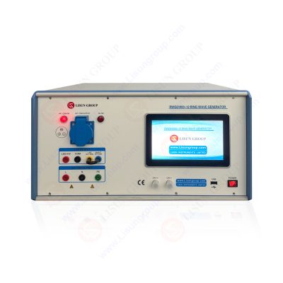
The LISUN RWG61000‑12 series ring wave simulator includes four models covering 4 kV and 6 kV output levels, equipped with single‑phase and three‑phase five‑wire coupling‑decoupling networks respectively, suitable for single‑phase household appliances, meters and three‑phase industrial equipment. This series complies with GB/T 17626.12‑2023, IEC 61000‑4‑12:2017, EN 61000‑4‑12:2017, GJB151B‑2013 and other standards. Main technical specifications are listed in Table 1.
Table 1 Main Specifications of RWG61000‑12 Series Ring Wave Simulator
| LISUN 모델 | RWG61000‑12 | RWG61000‑12T | RWG61000‑12A | RWG61000‑12AT |
| 최대 출력 전압 | 4kV | 4kV | 6kV | 6kV |
| 최대 출력 전류 | 333 A±10% @12 Ω;133 A±10% @30 Ω | 333 A±10% @12 Ω;133 A±10% @30 Ω | 500 A±10% @12 Ω;200 A±10% @30 Ω | 500 A±10% @12 Ω;200 A±10% @30 Ω |
| Voltage / Current Waveform | Open‑circuit voltage rise time: 0.5 μs; Short‑circuit current rise time: 0.2 μs‑1 μs; Oscillation frequency: 100 kHz±10% | Open‑circuit voltage rise time: 0.5 μs; Short‑circuit current rise time: 0.2 μs‑1 μs; Oscillation frequency: 100 kHz±10% | Open‑circuit voltage rise time: 0.5 μs; Short‑circuit current rise time: 0.2 μs‑1 μs; Oscillation frequency: 100 kHz±10% | Open‑circuit voltage rise time: 0.5 μs; Short‑circuit current rise time: 0.2 μs‑1 μs; Oscillation frequency: 100 kHz±10% |
| 출력 극성 | Positive, Negative, Alternating Positive‑Negative | Positive, Negative, Alternating Positive‑Negative | Positive, Negative, Alternating Positive‑Negative | Positive, Negative, Alternating Positive‑Negative |
| 위상 각 | Asynchronous, synchronous 0°‑360° adjustable | Asynchronous, synchronous 0°‑360° adjustable | Asynchronous, synchronous 0°‑360° adjustable | Asynchronous, synchronous 0°‑360° adjustable |
| 출력 임피던스 | 12 Ω, 30 Ω | 12 Ω, 30 Ω | 12 Ω, 30 Ω | 12 Ω, 30 Ω |
| Coupling‑Decoupling Network (CDN) | 16 A Single‑phase CDN | 20 A Three‑phase 5‑wire CDN | 16 A Single‑phase CDN | 20 A Three‑phase 5‑wire CDN |
| 전원 공급 장치 | AC 220 V (110 V optional) ±10%, 50/60 Hz | AC 220 V (110 V optional) ±10%, 50/60 Hz | AC 220 V (110 V optional) ±10%, 50/60 Hz | AC 220 V (110 V optional) ±10%, 50/60 Hz |
| 총 중량 | 약 28kg | 약 46kg | 약 45kg | 약 48kg |
As shown in parameters above, this ring wave simulator provides two standard output‑impedance settings: 12 Ω and 30 Ω, corresponding to test conditions with different source impedances specified in standards. It supports AC power‑frequency synchronous triggering from 0° to 360°, which can simulate scenarios where ring‑wave interference occurs at arbitrary phase angles of power‑frequency voltage and improve test reproducibility. The 4 kV version is suitable for household appliances and general industrial‑control equipment, while 6 kV models RWG61000‑12A and RWG61000‑12AT target power equipment and new‑energy products of higher severity levels. Single‑phase CDN fits small household appliances and electric meters; three‑phase five‑wire CDN is applied for frequency converters, three‑phase motors and other industrial equipment, covering a wide range of products.
RWG61000-12_알
3 Industrial Applications of Ring Wave Simulator
Ring wave simulators are widely adopted for product R&D, reliability verification and type‑testing across industrial control & power, new‑energy, consumer appliance, medical‑electronics and other sectors.
In industrial control and power‑equipment industries, PLCs, servo drives, industrial routers, energy meters and relay‑protection devices are required to complete power‑line immunity tests with ring wave simulators, simulating damped‑oscillation interference caused by motor start‑stop and transformer switching in factories. Tests can detect command delay, communication error and relay mis‑operation and evaluate insulation performance, avoiding on‑site equipment burnout and ensuring safe operation of production lines and power‑distribution systems.
In new‑energy and automotive‑electronics sectors, power‑input ports and CAN communication ports of AC/DC charging piles need ring‑wave immunity tests with ring wave simulators to simulate power‑grid disturbances and internal‑switching‑induced ring‑wave disturbances of charging piles, verifying whether charging interruption and communication failure occur. Automotive BMS and on‑board chargers (OBC) can also adopt ring wave simulators to reproduce transient oscillation interference of vehicle power‑supply systems and guarantee reliable operation of on‑board electronic components.
For household appliances and consumer electronics, refrigerators, air‑conditioners, washing machines, power adapters and smart sockets use ring wave simulators to reproduce ring‑wave disturbances generated by compressor start‑stop and high‑power‑appliance switching in residential power grids. It is verified whether equipment will crash or malfunction, and protection circuits of power ports are optimized in advance to improve reliability of consumer products.
Medical electronic equipment demands high operational reliability. Patient monitors, ultrasonic devices, infusion pumps and other medical instruments shall use ring wave simulators to simulate power‑grid ring‑wave disturbances caused by switching of large‑scale hospital equipment such as CT and MRI, verifying no data offset or false triggering occurs to guarantee diagnosis safety.
4 Practical Significance and Conclusion
Ring‑wave disturbance objectively exists in real‑world power‑supply networks, and numerous on‑site product failures originate from ring‑wave impact. The ring wave simulator delivers standardized and reproducible laboratory test solutions. Without building complex on‑site conditions, real‑world damped‑oscillation pulses can be simulated to complete immunity assessment for EUT, locate insulation weak points and protection‑circuit defects, and guide optimization on PCB layout, grounding design and surge‑protection‑component selection. The probability of on‑site equipment failure can be reduced from the R&D stage.
The LISUN RWG61000‑12 series ring wave simulator fully meets waveform requirements of national, military and international standards. Multiple single‑phase and three‑phase configurations satisfy requirements of R&D laboratories and third‑party test institutions. Ring‑wave immunity testing is not merely for compliance certification, but also a vital approach to enhance environmental adaptability and reliability of electrical and electronic equipment. With continuous popularization of industrial and new‑energy equipment, ring wave simulators will play an increasingly important role in EMC verification.
태그 :RWG61000-12귀하의 이메일 주소는 공개되지 않습니다. 필수 필드가 표시됩니다 *

 영어
영어 中文简体
中文简体 Русский
 Español
 Português
 Türkçe
 العربية
 Deutsch
 Polski
 Italiano
 Français
 한국어
한국어 ไทย
ไทย Tiếng Việt
 日本語
日本語